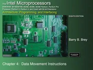
Chapter 5: Arithmetic and Logic Instructions
Chapter 5: Arithmetic and Logic Instructions. Introduction. We examine the arithmetic and logic instructions. The arithmetic instructions include addition , subtraction , multiplication , division , comparison , negation , increment , and decrement .

Chapter 5: Arithmetic and Logic Instructions
E N D
Presentation Transcript
Introduction • We examine the arithmetic and logic instructions. The arithmetic instructions include addition, subtraction, multiplication, division, comparison, negation, increment, and decrement. • The logic instructions include AND, OR, Exclusive-OR, NOT, shifts, rotates, and the logical compare (TEST).
Chapter Objectives Upon completion of this chapter, you will be able to: • Use arithmetic and logic instructions to accomplish simple binary, BCD, and ASCII arithmetic. • Use AND, OR, and Exclusive-OR to accomplish binary bit manipulation. • Use the shift and rotate instructions.
Chapter Objectives (cont.) Upon completion of this chapter, you will be able to: • Explain the operation of the 80386 throughthe Core2 exchange and add, compare and exchange, double-precision shift, bit test,and bit scan instructions. • Check the contents of a table for a match with the string instructions.
5-1 ADDITION, SUBTRACTION AND COMPARISON • The bulk of the arithmetic instructions found in any microprocessor include addition, subtraction, and comparison. • Addition, subtraction, and comparison instructions are illustrated. • Also shown are their uses in manipulating register and memory data.
Addition • Addition (ADD) appears in many forms in the microprocessor. • A second form of addition, called add-with-carry, is introduced with the ADC instruction. • The only types of addition not allowed are memory-to-memory and segment register. • segment registers can only be moved, pushed,or popped • Increment instruction (INC) is a special type of addition that adds 1 to a number.
Register Addition • When arithmetic and logic instructions execute, contents of the flag register change. • interrupt, trap, and other flags do not change • Any ADD instruction modifies the contents of the sign, zero, carry, auxiliary carry, parity, and overflow flags. Immediate Addition • Immediate addition is employed whenever constant or known data are added.
Memory-to-Register Addition • Moves memory data to be added to the AL (and other) register. Array Addition • Memory arrays are sequential lists of data.
Array Addition • Sequential lists of data. • A sequence of instructions written 80386 shows scaled-index form addressing to add elements 3, 5, and 7 of an area of memory called ARRAY. • EBX is loaded with the address ARRAY, and ECX holds the array element number. • The scaling factor is used to multiply the contents of the ECX register by 2 to address words of data.
Increment Addition • The INC instruction adds 1 to any register or memory location, except a segment register. • The size of the data must be described by using the BYTE PTR, WORD PTR, DWORD PTR, or QWORD PTR directives. • The assembler program cannot determine if the INC [DI] instruction is a byte-, word-, or doubleword-sized increment.
Addition-with-Carry • ADC) adds the bit in the carry flag (C) to the operand data. • mainly appears in software that adds numberswider than 16 or 32 bits in the 80386–Core2 • like ADD, ADC affects the flags after the addition • Figure 5–1 illustrates this so placement and function of the carry flag can be understood. • cannot be easily performed without adding the carry flag bit because the 8086–80286 onlyadds 8- or 16-bit numbers
Figure 5–1 Addition-with-carry showing how the carry flag (C) links the two 16-bit additions into one 32-bit addition.
Exchange and Add for the 80486–Core2 Processors • Exchange and add (XADD) appears in 80486 and continues through the Core2. • XADD instruction adds the source to the destination and stores the sum in the destination, as with any addition. • after the addition takes place, the original value of the destination is copied into the source operand • One of the few instructions that change the source.
Subtraction • Many forms of subtraction (SUB) appear in the instruction set. • these use any addressing mode with 8-, 16-, or 32-bit data • a special form of subtraction (decrement, or DEC) subtracts 1 from any register or memory location • Numbers that are wider than 16 bits or 32 bits must occasionally be subtracted. • the subtract-with-borrow instruction (SBB) performs this type of subtraction
Register Subtraction • After each subtraction, the microprocessor modifies the contents of the flag register. • flags change for most arithmetic/logic operations Immediate Subtraction • The microprocessor also allows immediate operands for the subtraction of constant data. Decrement Subtraction • Subtracts 1 from a register/memory location.
Subtraction-with-Borrow • A subtraction-with-borrow (SBB) instruction functions as a regular subtraction, except that the carry flag (C), which holds the borrow, also subtracts from the difference. • most common use is subtractions wider than 16 bits in the 8086–80286 microprocessors or wider than 32 bits in the 80386–Core2. • wide subtractions require borrows to propagate through the subtraction, just as wide additions propagate the carry
Figure 5–2 Subtraction-with-borrow showing how the carry flag (C) propagates the borrow.
Comparison • The comparison instruction (CMP) is a subtraction that changes only the flag bits. • destination operand never changes • Useful for checking the contents of a register or a memory location against another value. • A CMP is normally followed by a conditional jump instruction, which tests the condition of the flag bits.
Compare and Exchange (80486–Core2 Processors Only) • Compare and exchange instruction (CMPXCHG) compares the destination operand with the accumulator. • found only in 80486 - Core2 instruction sets • If they are equal, the source operand is copied to the destination; if not equal, the destination operand is copied into the accumulator. • instruction functions with 8-, 16-, or 32-bit data
CMPXCHG CX,DX instruction is an example of the compare and exchange instruction. • this compares the contents of CX with AX • if CX equals AX, DX is copied into AX; if CXis not equal to AX, CX is copied into AX • also compares AL with 8-bit data and EAX with 32-bit data if the operands are either 8- or 32-bit • This instruction has a bug that will cause the operating system to crash. • more information about this flaw can be obtained at www.intel.com
5-2 MULTIPLICATION AND DIVISION • Earlier 8-bit microprocessors could not multiply or divide without the use of a program that multiplied or divided by using a series of shifts and additions or subtractions. • manufacturers were aware of this inadequacy, they incorporated multiplication and division into the instruction sets of newer microprocessors. • Pentium–Core2 contains special circuitry to do multiplication in as few as one clocking period. • over 40 clocking periods in earlier processors
8-Bit Multiplication • With 8-bit multiplication, the multiplicand is always in the AL register, signed or unsigned. • multiplier can be any 8-bit register or memory location • Immediate multiplication is not allowed unless the special signed immediate multiplication instruction appears in a program. • The multiplication instruction contains one operand because it always multiplies the operand times the contents of register AL.
Multiplication • Performed on bytes, words, or doublewords, • can be signed (IMUL) or unsigned integer (MUL) • Product after a multiplication always a double-width product. • two 8-bit numbers multiplied generate a 16-bit product; two 16-bit numbers generate a 32-bit;two 32-bit numbers generate a 64-bit product • in 64-bit mode of Pentium 4, two 64-bit numbers are multiplied to generate a 128-bit product
16-Bit Multiplication • Word multiplication is very similar to byte multiplication. • AX contains the multiplicand instead of AL. • 32-bit product appears in DX–AX instead of AX • The DX register always contains the most significant 16 bits of the product; AX contains the least significant 16 bits. • As with 8-bit multiplication, the choice of the multiplier is up to the programmer.
A Special Immediate 16-Bit Multiplication • 80186 - Core2 processors can use a special version of the multiply instruction. • immediate multiplication must be signed; • instruction format is different because it contains three operands • First operand is 16-bit destination register; the second a register/memory location with16-bit multiplicand; the third 8- or 16-bit immediate data used as the multiplier.
32-Bit Multiplication • In 80386 and above, 32-bit multiplication is allowed because these microprocessors contain 32-bit registers. • can be signed or unsigned by using IMUL and MUL instructions • Contents of EAX are multiplied by the operand specified with the instruction. • The 64 bit product is found in EDX–EAX, where EAX contains the least significant 32 bits of the product.
64-Bit Multiplication • The result of a 64-bit multiplication in the Pentium 4 appears in the RDX:RAX register pair as a 128-bit product. • Although multiplication of this size is relatively rare, the Pentium 4 and Core2 can perform it on both signed and unsigned numbers.
Division • Occurs on 8- or 16-bit and 32-bit numbers depending on microprocessor. • signed (IDIV) or unsigned (DIV) integers • Dividend is always a double-width dividend, divided by the operand. • There is no immediate division instruction available to any microprocessor. • In 64-bit mode Pentium 4 & Core2, divide a 128-bit number by a 64-bit number.
A division can result in two types of errors: • attempt to divide by zero • other is a divide overflow, which occurs when a small number divides into a large number • In either case, the microprocessor generates an interrupt if a divide error occurs. • In most systems, a divide error interrupt displays an error message on the video screen.
8-Bit Division • Uses AX to store the dividend divided by the contents of any 8-bit register or memory location. • Quotient moves into AL after the division with AH containing a whole number remainder. • quotient is positive or negative; remainder always assumes sign of the dividend; always an integer
Numbers usually 8 bits wide in 8-bit division . • the dividend must be converted to a 16-bit wide number in AX ; accomplished differently for signed and unsigned numbers • CBW (convert byte to word) instruction performs this conversion. • In 80386 through Core2, MOVSX sign-extends a number.
16-Bit Division • Sixteen-bit division is similar to 8-bit division • instead of dividing into AX, the 16-bit number is divided into DX–AX, a 32-bit dividend • As with 8-bit division, numbers must often be converted to the proper form for the dividend. • if a 16-bit unsigned number is placed in AX, DX must be cleared to zero • In the 80386 and above, the number is zero-extended by using the MOVZX instruction.
32-Bit Division • 80386 - Pentium 4 perform 32-bit division on signed or unsigned numbers. • 64-bit contents of EDX–EAX are divided by the operand specified by the instruction • leaving a 32-bit quotient in EAX • and a 32-bit remainder in EDX • Other than the size of the registers, this instruction functions in the same manner as the 8- and 16-bit divisions.
64-Bit Division • Pentium 4 operated in 64-bit mode performs 64-bit division on signed or unsigned numbers. • The 64-bit division uses the RDX:RAX register pair to hold the dividend. • The quotient is found in RAX and the remainder is in RDX after the division.
The Remainder • Could be used to round the quotient or dropped to truncate the quotient. • If division is unsigned, rounding requires the remainder be compared with half the divisorto decide whether to round up the quotient • The remainder could also be converted to a fractional remainder.
5-3 BCD and ASCII Arithmetic • The microprocessor allows arithmetic manipulation of both BCD (binary-coded decimal) and ASCII (American Standard Code for Information Interchange) data. • BCD operations occur in systems such as point-of-sales terminals (e.g., cash registers) and others that seldom require complex arithmetic.
BCD Arithmetic • Two arithmetic techniques operate with BCD data: addition and subtraction. • DAA (decimal adjust after addition) instruction follows BCD addition, • DAS (decimal adjust after subtraction) follows BCD subtraction. • both correct the result of addition or subtractionso it is a BCD number
DAA Instruction • DAA follows the ADD or ADC instruction to adjust the result into a BCD result. • After adding the BL and DL registers, the result is adjusted with a DAA instruction before being stored in CL. DAS Instruction • Functions as does DAA instruction, except it follows a subtraction instead of an addition.
ASCII Arithmetic • ASCII arithmetic instructions function with coded numbers, value 30H to 39H for 0–9. • Four instructions in ASCII arithmetic operations: • AAA (ASCII adjust after addition) • AAD (ASCII adjust before division) • AAM (ASCII adjust after multiplication) • AAS (ASCII adjust after subtraction) • These instructions use register AX as the source and as the destination.
AAA Instruction • Addition of two one-digit ASCII-coded numbers will not result in any useful data. AAD Instruction • Appears before a division. • The AAD instruction requires the AX register contain a two-digit unpacked BCD number (not ASCII) before executing.
AAM Instruction • Follows multiplication instruction after multiplying two one-digit unpacked BCD numbers. • AAM converts from binary to unpacked BCD. • If a binary number between 0000H and 0063H appears in AX, AAM converts it to BCD. AAS Instruction • AAS adjusts the AX register after an ASCII subtraction.
5-4 BASIC LOGIC INSTRUCTIONS • Include AND, OR, Exclusive-OR, and NOT. • also TEST, a special form of the AND instruction • NEG, similar to the NOT instruction • Logic operations provide binary bit control in low-level software. • allow bits to be set, cleared, or complemented • Low-level software appears in machine language or assembly language form and often controls the I/O devices in a system.
All logic instructions affect the flag bits. • Logic operations always clear the carry and overflow flags • other flags change to reflect the result • When binary data are manipulated in a register or a memory location, the rightmost bit position is always numbered bit 0. • position numbers increase from bit 0 to the left, to bit 7 for a byte, and to bit 15 for a word • a doubleword (32 bits) uses bit position 31 as its leftmost bit and a quadword (64-bits) position 63
AND • Performs logical multiplication, illustrated by a truth table. • AND can replace discrete AND gates if the speed required is not too grea • normally reserved for embedded control applications • In 8086, the AND instruction often executesin about a microsecond. • with newer versions, the execution speed is greatly increased
Figure 5–3 (a) The truth table for the AND operation and (b) the logic symbol of an AND gate.
AND clears bits of a binary number. • called masking • AND uses any mode except memory-to-memory and segment register addressing. • An ASCIInumber can be converted to BCD by using AND to mask off the leftmost four binary bit positions.
Figure 5–4 The operation of the AND function showing how bits of a number are cleared to zero.
OR • Performs logical addition • often called the Inclusive-OR function • The OR function generates a logic 1 output if any inputs are 1. • a 0 appears at output only when all inputs are 0 • Figure 5–6 shows how the OR gate sets (1) any bit of a binary number. • The OR instruction uses any addressing mode except segment register addressing.
Figure 5–5 (a) The truth table for the OR operation and (b) the logic symbol of an OR gate.
Figure 5–6 The operation of the OR function showing how bits of a number are set to one.