Download
1 / 57
590 likes | 895 Vues
How good can Solar Cells be? Assessing Possibilities for Solar Cells by Identifying Basic Limitations to PV Performance. THANKS to many COLLEAGUES, esp. Pabitra Nayak Juan Bisquert, Un. Jaume, Antoine Kahn, Princeton Un. Lee Barnea, Ron Milo + other Weizmann Inst. colleagues

E N D
How good can Solar Cells be? Assessing Possibilities for Solar Cells by Identifying Basic Limitations to PV Performance THANKS to many COLLEAGUES, esp. Pabitra Nayak Juan Bisquert, Un. Jaume, Antoine Kahn, Princeton Un. Lee Barnea, Ron Milo + other Weizmann Inst. colleagues Bolko von Roedern, David Ginley, Keith Emery, Rommel Noufi NREL, US National Renewable Energy Lab Bernard Kippelen, Georgia Tech, Arie Zaban, Bar Ilan U.; K.L. Narasimhan, TIFR, 3G Solar & many others!
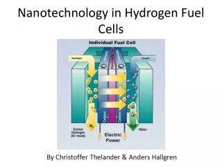
The Photovoltaic (PV) effect: Generalized picture Absorber High energy state e- • Metastable high and low energy states • Absorber transfers charges into high and low energy state • Driving force brings charges to contacts • Selective contacts contact contact one electron energy p+ Low energy state space • (1) cf. e.g., Green, M.A., Photovoltaic principles. Physica E, 14 (2002) 11-17
Types of PV Cells Primarily based on solid-state electronic material systems • Elemental Semiconductors • Single or multi-crystal • Polycrystalline • Amorphous thin film • Inorganic Compound Semiconductors • Single crystal • Polycrystalline thin film • Organic, Excitonic (molecules, polymer) • Polycrystalline • Interpenetrating network • Nanocrystalline; dye-sensitized Si,Ge (non) concentrator; single-& multi- junction (Ga,In)(As,P) Cu(In,Ga)Se2 CdTe homo- & hetero-junction; photo-electro- chemical; MIS Phenylene- vinylidene, PCBM++ Ru-dye+TiO2
next generations cheaper? simpler? Solar Cell (r)evolutions • 4.5 6 15 • nm great science 2nd generation CdTe, CIGS Quantum dot Cells 1st generation Si self-assembly & nano !! stabilization self-healing work horse poly-crystalline m cm micro-crystalline & amorphous single- & multi-crystalline
OUTLINE • PV cell performances today • Limits of PV solar energy conversion • Empirical guides to limits or possibilities • Losses in “excitonic” cells • Summary & Future
Lowest Loss Laboratory PV cells (1-4 cm2 except for tandems): Definition of efficiency: • ~[75%]25% single crystalline Si (28 % GaAs) • ~ [80%] 20 %singlejctn. PX thin films (CIGS, Si) • ~ [88%]~12% dye sensitized solar cell (DSSC) • ~ [90%] ~10% organic polymer / molecule • ~ [63%] 37% “big Mac” tandem triple junction • (~ [56%] 43.5% “bigger Mac” tandem, +concentration) Data from Solar Cell Eff #39, Progr in PV 2012
12.3% ETA cells / WIS
OUTLINE • PV cell performances today • Limits of PV solar energy conversion • Empirical guides to limits or possibilities • Losses in “excitonic” cells • Summary & Future
Possibilities for Technological Progress Efficiency(%)ManufacturerTechnology (area, if < 600 cm2) BEST rated/minimum commercial module /cell 19.6 /?? SunPower Single-crystal Si non-standard jnctn 78% 17.1 / 16.3 Sanyo Single-crystal Si HIP jnctn 74% 15.2 / 14.6 Kyocera Multi crystal Si standard junction 75% 13.4 / 12.7 Evergreen EFG(ribbon) Si standard junction 77% 12.2 / 10.8 First Solar CdTe 71 % 13.1 / 11.2 Miasole CIGS 67 % 12.6 /11.4 Q-cells CIGS 64 % 6.3 / ?? Kaneka a-Si single junction * 66 % 6.7 / 5.7 Uni-Solar a-Si, triple junction * 54 % * stabilized values 5#,** 3GSolar dye (225) ~40 % 3.9# Solarmer Organic polymer/ molecule (225) ~40 % # Pilot modules; few yrs stability; **not yet commercially available Nayak et al. Adv Mat. 2011 Module data from B v Roedern, NREL, 11/2011
WHY ? In Solar Cells Most Solar Energy is “Lost” as Heat Infra- visible ultra- -Red -violet (IR) (UV) Solar Energy Spectrum Photovoltaic Conversion is a Quantum (threshold) Conversion Process
in Solar Cells Most Solar Energy is “Lost” as Heat n h Single p-n junction solar cell e e - - high energy photon - partial loss Energy Energy e e - - h n - - useable photo p p - - type type voltage ( voltage ( qV qV ) ) n n - - type type low energy photon - total loss h h + + space O. Niitsoo
Losses in PV cell Current – Voltage Characteristics Eg Emission loss- (current) Carnot factor –TD Etendu; Photon entropy –TD ~0.3eV @RT, lack of concentration Electrical power out < Eg not absorbed >Eg thermalized After Hirst & Ekins-Daukes Prog.Photovolt:Res:Appl. (2010) Nayak et al. Energy Environ. Sci., 2012 (In Press)
Shockley-Queisser (SQ) Limit photosynthesis Prince, JAP 26 (1955) 534 Loferski, JAP 27 (1956) 777 Shockley & Queisser JAP (1961)
5 5 6 6 7 7 8 8 9 9 1 1 2 2 Bandgap (eV) What can we do? Make better use of sunlight: “Photon management” e.g., multi-junction photovoltaics tandem (stacked) spectral splitting (spatial) Four-junction device with bandgaps 1.8 eV/1.4 eV/1.0 eV/0.7 eV Theoretical efficiency > 52%
SPECTRAL SPLITTING A two junction, four terminal photovoltaic device for enhanced light to electric power conversion using a low-cost dichroic mirror Sven Rühle, Akiba Segal,Ayelet Vilan,Sarah R. Kurtz,Larissa Grinis, Arie Zaban,Igor Lubomirsky,and David Cahen JOURNAL OF RENEWABLE AND SUSTAINABLE ENERGY 1, 013106 2009
Electrical Performance with Dichroic Mirror A two junction, four terminal photovoltaic device for enhanced light to electric power conversion using a low-cost dichroic mirror Sven Rühle, Akiba Segal,Ayelet Vilan,Sarah R. Kurtz,Larissa Grinis, Arie Zaban,Igor Lubomirsky,and David Cahen JOURNAL OF RENEWABLE AND SUSTAINABLE ENERGY 1, 013106 2009
Electrical Performance with Dichroic Mirror Needed: cheap, high EG + high Vmax PV Cells A two junction, four terminal photovoltaic device for enhanced light to electric power conversion using a low-cost dichroic mirror Sven Rühle, Akiba Segal,Ayelet Vilan,Sarah R. Kurtz,Larissa Grinis, Arie Zaban,Igor Lubomirsky,and David Cahen JOURNAL OF RENEWABLE AND SUSTAINABLE ENERGY 1, 013106 2009
Improve performance using concentrated sunlight but … diffuse (scattered) radiation lost upon concentration
“Etendue” VOC loss (“photon entropy”) ΔF = ΔH – TΔS ΔqVOC=EG–kTln W=EG–kTln 46,200=EG–10.7 kT= 280 meV @ 300K Experiments on III-V alloys yield 350 -550 mV for Eg-Voc Hirst & Ekins-Daukes Proc. 24th Eur. PV Solar En. Conf. Hamburg
“Etendue” VOC loss (“photon entropy”) Richard King
OUTLINE • PV cell performances today • Limits of PV solar energy conversion • Empirical guides to limits or possibilities • Losses in “excitonic” cells • Summary & Future
Empirical Guide 1 Current
Current Limitation Harvest more photons from B. Kippelen, Georgia Tech
:LimitorOpportunity ? a From EQE * for best performing cell of given type Nayak et al. Adv. Mater., May 2011
:LimitorOpportunity ? a From EQE * for best performing cell of given type Nayak et al. Adv. Mater., May 2011
Maximal possible vs. experimental photocurrents Natural PS <~10-2 mA/cm2 PKN, JB, DC, 2011, AM Thanx 2 Lee B
Empirical Guide 2 Voltage
:LimitorOpportunity ? a From EQE * for best performing cell of given type PKN, JB, DC, 2011, AM
Voc / EG : Limit or Opportunity ? a From EQE * for best performing cell of given type PKN, JB, DC, 2011, AM
Voc / EG : Limit or Opportunity ? a From EQE * for best performing cell of given type PKN, JB, DC, 2011, AM
Shockley-Queisser or detailed balance limit COST as function of minimal excitation energy Wavelength [nm] WRONG COST: qVhν– qVOC [eV] Absorption Edge Energy [eV] S-Q based on R.Milo,WIS Thanx 2 Lee B
Geometrical illustration of solar spectrum loss due to “over-potential” Consider ~ 1 eV or 2 eV absorption edge “ Assume 1 eV “overpotential” shifts reference energy 1 eV to right small purple rectangle gives new optimal energy value. \ After Ron Milo, WIS PKN, JB, DC, 2011, AM
Geometrical illustration of solar spectrum loss due to “over-potential” Consider ~ 1 eV or 2 eV absorption edge “ Assume 1 eV “overpotential” shifts reference energy 1 eV to right small purple rectangle gives new optimal energy value. After Ron Milo, WIS PKN, JB, DC, 2011, AM
VMP / EG : Limit or Opportunity? a From EQE * for best performing cell of given type Nayak et al. Adv. Mater., May 2011
VMP / EG : Limit or Opportunity? a From EQE * for best performing cell of given type Nayak et al. Adv. Mater., May 2011
Shockley-Queisser or detailed balance limit LOSS as function of minimal excitation energy qVhν– qVoperation(=MP) [eV] Absorption Edge Energy [eV] S-Q based on R.Milo,WIS PKN, JB, DC, 2011, AM Thanx 2 Lee B
OUTLINE • PV cell performances today • Limits of PV solar energy conversion • Empirical guides to limits or possibilities • Losses in “excitonic” cells • Summary & Future
Shockley-Queisser or detailed balance limit LOSS as function of minimal excitation energy ............... Includes basic add’l loss of amorphous/disordered material qVhν– qVoperation(=MP) [eV] PS: natural photsynthesis S-Q from R.Milo,WIS PKN, JB, DC, 2011, AM
Why / how do we loose with the excitonic cells?
Cathode D D A Anode - Substrate Light StaticDisorder Bulk heterojunction cell Paul W. M. Blom et al.
Consider electron transfer & Vibronic relaxation D*A D+A- λrel (1) λ λ = λrel (1) + λrel (2) ΔG* Vibronic relaxation after electron transfer A- ΔG0 Energy (eV) Energy (eV) DA Eg Loss = λrel (hole) + λrel (electron) λrel (hole) = ~150 meV (UPS) λrel (electron)= ~150 meV (DFT) λrel (2) ΔG0rec A Nuclear co-ordinate Nuclear co-ordinate Nayak et al., EES, in press
Static and Dynamicdisorder Tail states After Kera, Yamane and Ueno Progress in Surface Science, 2009 Nayak et al., EES, in press
p/n vs. excitonic solar cells Wannier exciton Frenkel exciton Exciton binding energy >> kT → requires donor/acceptor, (D/A) type structure Exciton binding energy < kT → dissociation by space charge region E-field 3 LUMO (D) 2 LUMO (A) 1 ΔD/A Energy (eV) Energy (eV) HOMO (D) CBM HOMO (A) 3 Donor Acceptor EFp VBM p n Organic Inorganic
Electron-hole pair: Organic vs. Inorganic PV cells Exciton binding energy >> kT → requires donor/ acceptor, (D/A) type structure Exciton binding energy < kT → dissociation by space charge region E-field MOLECULAR PICTURE Organic semiconductor Inorganic semiconductor from A. Kahn, Princeton U
p/n vs. excitonic solar cells ORGANIC INORGANIC Exciton binding energy ~ 10 meV ~ 0.1-0.3 eV EFn • lowdielectricconstant • exciton splitting • includes jiggling & wiggling • high dielectric constant • minority carrier device dielectric constant from B. Kippelen, Georgia Tech
Origin of VOC {LUMO(A) – HOMO(D)gap} Voccorrelation Evac EA IE LUMO EF D Δ A EF HOMO Rand et al., Phys. Rev. B 75, (2007) Δ= IE(D) – EA(A) – EBA/2 (?) VOC = IE(D)–EA(A)–(≥0.3)? Afer A. Kahn, Princeton U
Nayak et al., EES, in press Origin of VOC VocasJ0& J00 • k :rate of charge transfer (s-1) • e: electron charge (C) • NDA: surface density of DA complexes[cm-2] • G0Gibbs free energy • reorganization energy, relaxation due to vibronic modes • Vifelectronic coupling after B. Kippelen, Georgia Tech
OUTLINE • PV cell performances today • Limits of PV solar energy conversion • Empirical guides to limits or possibilities • Losses in “excitonic” cells • Summary & Future
Summary • There are limits, beyond Shockley-Queisser for photo-conversion with organics (OPV, DSSC, PS, AP) • static disorder ~ 0.2-0.3 eV • dynamic disorder • vibronic coupling ~ 0.2-0.3 eV • low dielectric constant~ 0.1 -0.3 eV • Σ = 0.5 - 0.9 eV; cf. 1.05 eV ! Nayak et al. Adv. Mater., May 2011 PKN, JB, DC -TBP