Download

1 / 48
641 likes | 1.87k Vues
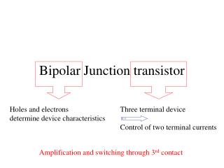
Base Current Controls Output current. BJT, Bipolar Junction Transisor. Bollen. BJT transistorman Transistor types Bipolar Junction Transistor BJT models parameters water model NPN and PNP operation modes switch open switch closed. BJT linear, controlled current source

E N D
Base Current Controls Output current BJT, Bipolar Junction Transisor Bollen
BJT transistorman Transistor types Bipolar Junction Transistor BJT models parameters water model NPN and PNP operation modes switch open switch closed BJT linear, controlled current source active operation characteristics DC input characteristics ac input characteristics BJT DC biasing circuits base bias base bias + collector feedback base bias + emitter feedback voltage divider AGENDA Bollen
BJT, transistor man Bollen
Output current controlled by input current BJT= Bipolar Junction Transistor FET = Field Effect Transistor TransistorTypes Output current controlled by input voltage Bollen
Transistor=TransferResistor BJT, Bipolar Junction Transisor BE Forward bias, BC Reverse bias So low ohmic high ohmic Bollen
BJT, Bipolar Junction Transisor Emitter = Sent electrons Base = Base Collector = Get electrons Bollen
BJT, Models Bollen
BJT, parameters Bollen
BJT, Water model Bollen
BJT, Water model Bollen
BJT, NPN and PNP Bollen
Cut-off and saturation; BJT is used as a switch Active operation Quiecent Point; BJT is used as a controlled current source, or analog amplifier BJT, Operation modes Bollen
BJT, Switch open Bollen
BJT, Switch closed Bollen
BJT, active operation Bollen
DC model ac model BJT, characteristics DC model; Vbe = 0V7 Ube, Uce, Ic, Ib, Ie Capitals ac model; re = 26mV/Ie ube, uce, ic, ib, ie Low cases Bollen
BJT, DC input characteristics Vbe = 0V7 Bollen
BJT, AC input characteristics re = 26mV/Ic The dynamic resistor can be calculated by the DC current Ic Bollen
BJT, characteristics Bollen
BJT, DC biasing circuits A base bias B base bias + emitter feedback C base bias + collector feedback D voltage divider Bollen
BJT, base bias, introduction Base current determined by Vcc, Rb and Vbe Bollen
BJT, base bias Calculate Ib and then Ic Ic directly dependent on ß variation So, for stability a “bad” circuit Bollen
Q-point = Quiecient point = Working point BJT, base bias load line Load line is the loading of the transistor seen from Uce (>0V7) Vcc and Rc determines the; “open voltage” and the “short circuit current” Bollen
Reliable circuit = Q-point stability BJT, base bias load line Load line is the loading of the transistor seen from Uce (>0V7) Vcc and Rc determines the; “open voltage” and the “short circuit current” Bollen
Vce always > 0V7 BC junction REVERSE BJT, base bias load line If Rc too big, transistor in saturation; then; Bollen
Vce always > 0V7 BC junction REVERSE BJT, base bias load line If Vcc too small, transistor in saturation; then; Bollen
Calculate; Ib, Ic URc, Uc, Uce Draw output caracteristic Calculate now; Uce if ß = 40 How many % did Uce Change BJT, base bias example Ib = 47 uA, Ic = 2,35 mA, URc = 5,17 V, Uc = 6,83 V, Uce = 6,83 V Uce (for ß = 40) = 7,86 Ξ 15 % Bollen
BJT, base bias example Ib = 33 uA, Ic = 2,9 mA URc = 7,9 V, Uc = 8,1 V Rb = 282,5 kΩ, Ic = 3,2 mA, Rc = 1,855 kΩ Bollen
BJT, base bias example ß = 200, VRc = 8,8 V Vcc = 16 VRb = 765 kΩ Bollen
BJT, base bias + emitter feedback Base current determined by Vcc, Rb, Vbe and Ve More stable for ß variations, than base bias. Bollen
BJT, base bias + emitter feedback Always calculate in the smallest current Ib !! Bollen
BJT, base bias + emitter feedback Load line is the loading of the transistor seen from Uce (>0V7) Vcc, Rc and Re determines the; “open voltage” and the “short circuit current” Bollen
Calculate; Ib, Ic URc, Uc, Ue, Uce Draw output caracteristic BJT, base bias + emitter feedback example Ib = 6,2 uA, Ic = 0,74 mA, URc = 8,9 V, Uc = 7,1 V, Ue =-0,9 V, Uce = 8,0 V Bollen
Calculate; Ib, Ie URe, Ue, Uce Draw output caracteristic BJT, base bias + emitter feedback example Ib = 24 uA, Ie = 2,9 mA, URc = 3,5 V, Ue = -2,5 V, Uce = 2,5 V Bollen
BJT, base bias + collector/emitter feedback If Ic > then Uc < then Ib < If Ic > then Uc < and Ue > then Ib < Bollen
BJT, base bias + collector feedback Always calculate in the smallest current Ib !! The current through Rc is not Ic but Ic + Ib, so (β+1)Ib !!! If Ic rises for any reason, then Uc falls and also Ib decreases, so then Ic decreases Bollen
Calculate; Ib, ß, Ic Draw output caracteristic BJT, base bias collector feedback example Ib = 13 uA, ß = 196, Ic = 2,5 mA Bollen
BJT, base bias collector/emitter feedback Always calculate in the smallest current Ib !! Bollen
Calculate; Ib, Ie URc, Uc, Ue, Uce Draw output caracteristic BJT, base bias collector/emitter feedback ex Ib = 11,8 uA, Ie = 1,1 mA URc = 5,2 V, Uc = 4,8 V Ue = 1,3 V, Uce = 3,5 V Bollen
Vb is a stable voltage - 0,7 V = so Ve is a stable voltage Ie is determined by Ve/ Re Ic = Ie . ß/(ß+1) Ic is very stable and nearly independent to ß variation, as long as ß is BIG in value BJT, voltage divider 2 methods of calculating Ic - neglegting Ib, use voltage divider - not neglecting Ib and use thevenin Bollen
BJT, voltage divider, neglect Ib So neglegt Ib to R2, or in general Ri >> R2 In practice 10 times bigger Bollen
Thevenin resistance R1 // R2 62k // 9k1= 7k9 BJT, voltage divider, exact, thevenin Thevenin voltage Bollen
BJT, voltage divider, exact, thevenin 7k9 2V0 Ib = 20 uA Bollen
Thevenin resistance = 6k8 Thevenin voltage = 3V1 Ib = 18,8 uA Ic = 2,25 mA re = 11,5 Ω URc = 7V4 Uc = 10V6 Ue = 2V3 Uce = 5V1 BJT, voltage divider, example Bollen
Thevenin resistance = 255k Thevenin voltage = 0V0 Ib = 14,3 uA Ic = 1,9 mA re = 14 Ω URc = 17V3 Uc = 0V7 Ue = -3V7 Uce = 4V4 BJT, voltage divider, example Bollen
BJT Bollen
BJT Bollen