GROUND PROCESSING TOOL MODULE - DESIGN
GROUND PROCESSING TOOL MODULE - DESIGN. Ground Processing Tool. AIM: remove landmines from the lane where the machine is working and to process soil at constant depth (100mm). Mine disposal problems: - tracks do not have to pass over mines already lift up

GROUND PROCESSING TOOL MODULE - DESIGN
E N D
Presentation Transcript
Ground Processing Tool AIM: remove landmines from the lane where the machine is working and to process soil at constant depth (100mm) Mine disposal problems: - tracks do not have to pass over mines already lift up 2 possibilities: collect mines, leave mines beside leave mines beside arrow rake Analysis of similar tools: agriculture: potato digger military: mine plough
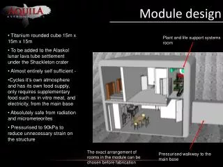
Ground Processing Tool - shape • Implications: • weight transfer soil tool interaction force contributes transferring weight from rear to front (undesirable) • 2. depth control depends on hitch system using semi mounted, plus depth control wheel helps reducing weight transfer from rear to front 3. soil processing cutting and sieving: cutting soil at required depth and pass it through a sieve allowing any object bigger then a mine to be lifted up space between tines: 40mm
Ground Processing Tool - shape To simplify manufacturing: plane shapes the arrow rake is defined by two angles: Rake angle = between the tool and the horizontal (ground), in the longitudinal vertical plane Side angle = between the tool and the vertical plane, on the horizontal plane
Ground Processing Tool - shape I design: Rake angle = 20° Side angle = 30° Crap-up prototype: cardboard model and test in sand
Ground Processing Tool - shape II design: Side angle = 50°, as small side angle causes the soil to move to the side Rake angle = 30°, increased to keep the distance of tool tip from the frame relatively small - 2 different tine positions for testing which one works better - open cage depth wheel, mounted on friction arm for reducing damages from possible blast - possibility to add vibratory motion: cylinder or bumpy wheel
Soil-tool interaction force, S • Estimation of force required to push/pull ground processing tool, S: • I. Agricultural Machinery Management Data, ASAE D497.5 FEB2006, published by ASABE: • Where, F is a dimensionless soil texture adjustment parameter whose value is given in ASABE tables, A, B and C are machine specific parameters, given in ASABE tables, V is field speed, W is machine width, T is tillage depth. For pushing a tool 1200mm wide, at 100mm depth, at 1.1km/h, in fine textured soil • S = 2500N • II. Extrapolating data regarding a 19 tines scarifier fitted with 150mm wide dart points, Kruger&Palmer, 1982: • S = 2000N • III. The Australian Tillage and Trafficability Data Bank – regression eq.’s: • For scarifiers in medium soil, optimal moisture, speed range of 0.53-3.27m/s, depth range of 29-150mm, with Variance Accounted for 47.6%, • Where, V is ground speed [m/s], D is working depth [mm] • S = 3000N
Soil-tool interaction force, S • Estimation of direction of soil-tool interaction force, S: • From Payne 1959: for rake angle = 30° soil-tool interaction force angle = 17°