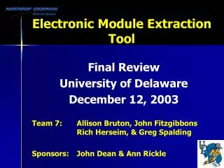
Electronic Module Extraction Tool
Electronic Module Extraction Tool. Final Review University of Delaware December 12, 2003 Team 7: Allison Bruton, John Fitzgibbons Rich Herseim, & Greg Spalding Sponsors: John Dean & Ann Rickle. Outline. Project Background Benchmarking Summary Project Scope Preliminary Concepts

Electronic Module Extraction Tool
E N D
Presentation Transcript
Electronic Module Extraction Tool Final Review University of Delaware December 12, 2003 Team 7: Allison Bruton, John Fitzgibbons Rich Herseim, & Greg Spalding Sponsors: John Dean & Ann Rickle
Outline • Project Background • Benchmarking Summary • Project Scope • Preliminary Concepts • Design Recommendations • Extraction Tool • Testing and Analysis • Project Management • Transition Plan • Questions
Project Background • Northrop Grumman • Worldwide leader in global defense electronic systems • No handheld tools exist for extraction of electronic modules in horizontal configuration • Purpose of tool • Extract electronic modules within tight tolerance for repair Cap Board Ceramic Base Ring Frame Electronic Module ** Module size relative to half dollar
Critical Issues • Tight Spacing • Fragile Parts • Module is composed of metallic & non-metallic layers Cap Board: Non-Metallic Ring Frame: Metallic Ceramic Base: Non-Metallic Side View of Electronic Module
Constraints • Minimize damage to cap board & module • Maintain tight position tolerance • Meet OSHA regulations
Mission Statement “To design a handheld extraction tool for electronic modules”
Lessons Learned from Benchmarking • Phase One • Variety of Integrated Circuit (IC) extractor devices on the market Dual In-Line Package IC Extractor Tool Advanced Tweezer Extractor Basic IC Extractor Self-Contained Vacuum Pickup Tool
Lessons Learned from Benchmarking (continued) • Phase Two • Gained greater understanding of: • Material properties of each layer within electronic module • Electromagnets • Magnetic analysis • Phase Three • Gained greater understanding of: • Ergonomic design - OSHA • Magnet pull force • Plate analysis Rare Earth Magnet Electromagnet
Customers, Wants & Metrics Wants Target Value Extraction force (lb) >3.6 Stress on ring frame (psi) <50,000 Bending force on pins/tubes (lb) <0.17 Tolerance fit check Yes Metrics
Project Scope Repair System Design recommendations for new electronic module Repair Operation Operation Manual Extract Module Ergonomics Extractor Interface Force Application Simple Superstructure
4 Preliminary Concepts 2 Concept Finalists • Clamping Device • Physical testing proved required extraction force (3.6 lbs) was not met • Hook Device • Analysis predicted tool interface would deform • Suction Device • Interaction between suction & cap board could damage module • Magnetic Device • Needed further investigation • After further development……
Design recommendations for electronic module • Ceramic Board • Two chamfered corners • Allows pin placement • Capboard • Cutouts • Accommodates magnetic interface • Capacitors and Fuses • Realignment • Optimizes capboard cutouts Capacitors & Fuses Cap Board Ring Frame Ceramic Base Revised Electronic Module
3.5” 10” Extraction Tool – Prototype • Force Application • Human powered • Push rod and knob • Superstructure • Linear ball bearing • Linear guides • Support pins • Magnetic Interface • Rare earth magnets
Extraction Tool - Operation 3 Simple Steps • Obtain proper extraction position • 2) Compress knob until contact is made with the exposed ring frame • 3)Pull knob up extracting the module
Testing and Analysis • Magnetic Interface Test • Finite Element Analysis on Ring Frame • Bending Analysis • Tolerance Fit Check
Magnetic Interface Test • Purpose: • Prove that the magnetic interface can withstand the required extraction force F Load Cell Magnet Holder Ring Frame Tested Magnet Sample .25” Dia x .75” Test Fixture
Magnetic Interface Test Required 3.6 lbs Metric & Target Value Satisfied ~ 5.4 lbs • Extraction force > 3.6 lbs • Conclusion: • Extraction force of 5.4 lbs achieved • Safety factor of 1.5 provided
FEA – Ring Frame • Purpose: • Prove that the maximum stress in the ring frame is below its yield strength Metric & Target Value Satisfied • Max stress in the ring frame < 50,000 psi Stress Distribution Magnet Locations • Conclusion: • Maximum stress present in the ring frame ~14,000 psi • Safety Factor of 3.57 provided
Bending Analysis • Purpose: • Prove that the ceramic base deflection will not plastically yield the module pins Metric & Target Value Satisfied • Force on pins < 0.17 lbs • Conclusion: • Worst ceramic deflection ~1.82 E-4 in. • Resultant force on pins ~0.00025 lbs • Provides a safety factor >>10
Tolerance Fit Check • Purpose: • Prove that the support pins of the extraction tool fit in the four corners of the rapid prototype module Rapid Prototype Module Support Pins • Conclusion: • Passed tolerance fit check Tool Fit Check
Device Ergonomics Tool Design Knob 2.0” Proper neutral wrist position Horizontal work surface • 2.0” diameter fell within acceptable diameter range for power grip use • Met OSHA regulations • Appropriately designed hand tool so wrist can remain straight • Met OSHA recommendations
Project Completed in a Team Effort Development Analysis Testing & Prototyping
Transition Plan • Operation Manual • Ergonomic issues • Improved handle design • Tool Alterations • Improved support pins • Reduced tool weight • Limited linear motion • Module Recommendations • Ceramic chamfers • Cap board redesign Capacitors & Fuses Cap Board Ring Frame Ceramic Base
Summary • Reviewed Project Background • Explored Benchmarking • Presented Project Scope • Explored Preliminary Concepts • Provided Design Recommendations • Discussed Extraction Tool • Demonstrated Analysis & Testing • Discussed Project Management • Presented Transition Plan
Acknowledgements • Northrop Grumman Sponsors • John Dean & Ann Rickle • Advisor – Dr. Wilkins • Senior Design Staff • Dr. Glancey • Dr. Keefe • Mr. Cloud • Steve Beard • Roger Stahl
Extraction Force Calculation Extraction Force ~0.11 lbs
Temperature Consideration • Maximum required operating temperature of extraction tool: • Neodymium Iron Boron rare earth magnets maximum operating temperature: ≤ 60oC 80oC
Extraction Tool – Fabricated Parts Before After Top Push Rod Side Coupler Bottom Magnet Holder
Clamping Interface Test Max Extraction Force = 3.5 lbs < 3.6 lbs Required 3.6lbs
FEA – Clamping Force Compressive Forces on Ring Frame Stress Distribution Max stress ~4000 psi << 50000 psi (ring frame)
Ring Frame Used in Clamping Test Actual Ring Frame Tested Ring Frame
Extraction vs. Insertion • Insertion is considered a small hand operation • Easier to insert correctly than extract • Northrop Grumman main focus is extraction
Magnet Interface Testing ¼ the Required Extraction Force ~ 1.6 lbs
Tolerance Analysis • Purpose: • Prove that the support pins of the extraction tool fit in the four corners of the 0.017 in2 area tolerance Metric & Target Value Satisfied • Tool support pins fit in the 0.017 in2 area tolerance Support Pin Tolerances
Linear Motion Test • Purpose: • Ensure magnets move in a linear fashion • Results: • Max deflection at magnet holder 0.0035” • Conclusion: • Tool will extract in a linear fashion Dial Indicator Magnet Holder Test Set Up
Basic Design Features • Grip/Handle-User Interface • Extraction Structure • Module-Tool Interface
3.5” 10” Extraction Tool - Prototype Knob Linear Bearing Handle Magnets