Download
1 / 54
540 likes | 560 Vues
These slides serve as a template for presenting information required in a Preliminary Design Review for a deployable sensor payload team. Each section can be expanded into additional slides as needed, maintaining a clean format with the team/school logo, page numbers, and customizable background. Avoid cramming topics into one slide and submit in PDF format for compatibility. Emphasize trade studies in PDR and final design in CDR. Utilize consistent units and maintain clarity and organization throughout the presentation.

E N D
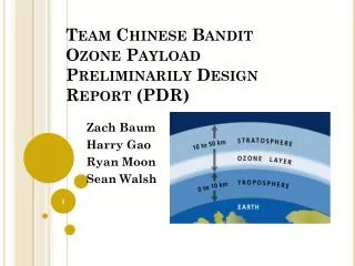
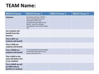
Deployable Sensor Payload PDR Team Name
Instructions Slides are a template describing information needed. Each section can be expanded into more slides as needed. Don't try cramming each listed topic on the same slide. Place team/school logo in the top left corner. Put page numbers on the slides. Formatting and background can be customized. Do not include animations or videos as reviewers may not have compatible software. Submit PDR in pdf format for maximum compatibility. A PDR should focus on trade studies, CDR should focus on final design. Use consistent units (metric or standard). Do not include this slide in the presentation. Yes, some one will.
Presentation Outline Provide a simple outline of the presentation Indicate team member(s) who will present each section
Team Organization Single slide listing team members and role Can use an organization chart
Acronyms Provide a list of acronyms used throughout the presentation Used as reference only. Does not need to be read through
Mission Summary Overview of mission objectives Include any external objectives
System Requirement Summary Overview of system (mission) level requirements Use table to demonstrate understanding of requirements Include requirements for the payload Include requirements for the rocket
System Level Trade and Selection Present two preliminary overall design concepts considered Configurations of rocket and Payload Break up into two teams to come up with independent designs Present criteria for final configuration selection Include sketches and diagrams of various concepts considered.
System Concept of Operations Provide overview of operations of the system from launch to landing to Payload operations. Launch and descent operations Payload operations Post-launch recovery Simple flow diagrams and cartoons are a good way to present the CONOPS
Design of Rocket • Describe overall rocket design • A drawing of the rocket identifying all of its components and dimensions • Length and diameter • Identify major components and locations • Nose cone • Number of fins and size • Location and size of rail buttons • Location of avionics bay if using electronics deployment with altimeter(s) • Total on the pad weight of the rocket with the primary and backup motors. • This includes: • All recovery harnesses and parachutes • Primary or backup motor
Design of Rocket (continued) • Identify the rocket’s stability. The center of gravity (CG) must be ahead of the center of pressure (CP) by at least one diameter (caliber) of your rocket. • With primary motor • With backup motor • Motor retention method • Friction fit is specifically disallowed
Rocket Materials • List of materials used: • Airframe material • Fin material • Nose cone material • Type of adhesives used • Rail button source and material
Rocket Recovery System • Parachute selection • Size of and how determined • Identify method for protecting parachute and rationale for choice • Dual deploy? • What is the expected descent rate(s) • Harness • Show drawing of recovery harnesses for each part of rocket • Type of shock cord, lengths and strengths • Identify linkages and load limits • Attachment points, eyebolts, fender washers, etc. and their mounting methods
Rocket Recovery System Deployment Method • Document method of initiating recovery • Altimeter(s) • Parachute release mechanism • Motor ejection - specify motor delay in seconds for • Primary motor • Secondary motor • Any rockets using VMAX motors must use an altimeter that deploys the parachutes as per Tripoli and NAR rules.
Rocket Recovery Electronics - if used • Identify which commercial altimeter(s) will be used • Show wiring diagram of altimeters with charges • Document the number and size of the pressure ports for altimeter • Document altimeter preparation steps. • Specify the quantity of black powder to be used to separate each section • Specify the volume of the section to be pressurized with calculated pressure level • Document charge size testing and results • Specify how sections are secured before the ejection charges separate sections • friction fit • shear pins - number and size • Other • Identify how charges are fired • e-matches • other
Rocket Motor Selection • Identify primary motor selection • Calculate thrust to on pad weight ratio using average thrust of the primary motor • Thrust to weight ratio must be a minimum of 5:1 • Identify back up motor selection and what changes to rocket would be required to successfully comply with contest rules • Calculate thrust to on pad weight ratio using average thrust of the backup motor • Thrust to weight ratio must be a minimum of 5:1 • Include a simulation plot for the primary motor • Include a simulation plot for the backup motor
Payload Design Overview Show block diagram or picture of payload Identify major components Dimensions
Altitude Recording Altimeter • Identify the commercial altimeterto be used to officially record the rocket’s altitude • If using a commercial altimeter for deployment, it can be designated the altitude recording altimeter
Mechanical Layout and Component Trade and Selection Trade study of mechanical design and structure of payload Show structure of Payload Identify location of major components Identify major mechanical parts Show at least two concepts Indicate selection and reasons for selection
Mechanical Materials List Identify materials used for mechanical structure
Payload Mass Budget Show mass of all components of the selected design Mass of each structural element in grams Sources/uncertainties – whether the masses are estimates, from data sheets, measured values, etc. Total mass of all components and structural elements Margin : The amount of mass (in grams) in which the mass budget meets, exceeds, or falls short of the mass requirement
Payload Electronics Electronic block diagram showing all major components Processors Memories Sensors Drivers for mechanisms and actuators
Processor and Memory Trade and Selection Identify at least two different processors considered Specs of processor Power consumption Speed Interfaces Indicate selected design and reasons for selection
PayloadPressure Sensor Trade Trade study of at least two sensors to be used in payload for measuring altitude Indicate selected sensor and reasons for selection
PayloadHumidity Sensor Trade Trade study of at least two sensors to be used in payload for measuring humidity Indicate selected sensor and reasons for selection
PayloadTemperature Sensor Trade Trade study of at least two sensors to be used in payload Indicate selected sensor and reasons for selection
PayloadGPS Trade Trade study of at least two sensors to be used in payload Indicate selected sensor and reasons for selection
Camera Sensor Trade study of at least two sensors to be used in payload Indicate selected sensor and reasons for selection Show how to compensate for the payload spin
Bonus Wind Sensor Identify two wind sensor designs Indicate if no bonuses are being attempted
Payload Radio Trade and Selection Trade study for radio selection Show at least two options Identify frequency operation Identify selection and reason for selection
Payload Radio Antenna Trade and Selection Trade 2 • Trade study of antennas for the Payload • Type of antenna • Mounting location • Potential interference issues with structure • Antenna Gain • Identify selection and reasons for selection • Trade 1 • Trade study of antennas for the Payload Type of antenna Mounting location Potential interference issues with structure Antenna Gain • Identify selection and reasons for selection Trade Decision (#1 or #2) Supporting evidence for decision (Why?)
Payload Power Trade and Selection Trade study of power sources for Payload Battery selection and configuration Power capacity Mounting method Protection circuits Short circuit Over-discharge for lithium ion cells Identify selection and reason for selection
Payload Power Distribution Electrical Power System Design Regulators Power distribution to subsystems, mechanisms, actuators Power management
Payload Power Budget List power consumption of all electrical components All values are to be in watt-hours Compare to capacity of battery in watt-hours Identify how long Payload can operate on batteries
Payload Software Design Flow Chart of software Identify software states and how software transitions to each state Power up Integration Launch Transmission (bonus) Landing
Software Development Plan Describe plan for software development Include Prototyping and prototyping environments Software subsystem development sequence Development team Test methodology
Payload Integration Construction of payload section Integration Process
Ground Station Design Show block diagram of ground station Identify all major components
Ground Station Antenna Trade and Selection Key trade issues for antenna trade and selection Type of antenna Antenna pattern Range calculation Identify if mounted or hand-held
Ground Station Software Telemetry display (show prototype of display) Identify any commercial or open source software packages to be used Real time plotting if implemented
Ground Station Portability Explain how ground station can be made portable Battery operation life of ground station
Payload Testing Describe testing of Payload subsystems Describe testing during subsystem integration Describe functional testing
Rocket Testing Describe testing of rocket Parachute deployment testing Payload Deployment testing Flight test