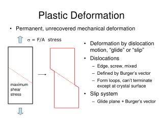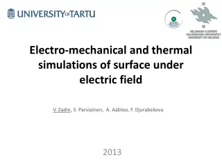
Simulation of plastic deformation of surfaces under high electric field
160 likes | 378 Vues
Simulation of plastic deformation of surfaces under high electric field. Simon Vigonski , Mihkel Veske, Vahur Zadin, Alvo Aabloo, Flyura Djurabekova. Outline. Introduction and motivation Fe precipitate effect on surface geometry Void formation near precipitate Internal stress distribution

Simulation of plastic deformation of surfaces under high electric field
E N D
Presentation Transcript
Simulation of plastic deformation of surfaces under high electric field Simon Vigonski, Mihkel Veske, Vahur Zadin, Alvo Aabloo, Flyura Djurabekova
Outline • Introduction and motivation • Fe precipitate effect on surface geometry • Void formation near precipitate • Internal stress distribution • Dynamic rising tip simulations in FEM and MD • Stress near surfaces in FEM • Validation of FEM surface stress model Simon Vigonski MeVArc 2015
MD simulations with voids and precipitates • Near-surface voids are dislocation nucleation sites under external stress. • Dislocations propagate to the surface and result in surface modification and protrusion growth. • Study dislocation nucleation and surface geometry modification with other defects. • Dislocations on precipitates • Stress distribution around voids Simon Vigonski MeVArc 2015 Pohjonenet al.2013 J. Appl. Phys.114 033519
Method - molecular dynamics • Classical molecular dynamics with LAMMPS, PARCAS and HELMOD • InteractionsbetweenatomsgovernedbyNewton’sequations • Exaggerated external forces are often needed to achieve reasonable calculation time • EAM potentials for Cu http://galleryhip.com/cubic-crystal-system.html Anisotropic properties due to FCC crystal structure of Cu Simon Vigonski MeVArc 2015
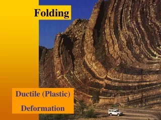
Fe precipitate - plateau formation • Dislocations nucleate around the precipitate at relatively high external stress. • Plateau forms on the surface from the interaction of two precipitates (here periodic images) • The plateau can grow with increasing stress. Simon Vigonski MeVArc 2015 S. Vigonskiet al., Modelling Simul. Mater. Sci. Eng., vol. 23, no. 2, p. 025009, Mar. 2015.
Fe precipitate - void formation • At high stresses voids appear at the Fe-Cu interface. • The volume grows until material failure Simon Vigonski MeVArc 2015 S. Vigonskiet al., Modelling Simul. Mater. Sci. Eng., vol. 23, no. 2, p. 025009, Mar. 2015.
Fe precipitate – internal stress distribution • Stress is concentrated around the precipitate. • Stress concentrations result in dislocation nucleation and voids. • Noise due to thermal motion of atoms. Simon Vigonski MeVArc 2015 S. Vigonskiet al., Modelling Simul. Mater. Sci. Eng., vol. 23, no. 2, p. 025009, Mar. 2015.
Fe precipitate – effects of external stress Stress (GPa) collapse 8.5 8.2 voids 7.2 plateau Lower stress = lower probability of dislocation nucleation 6.2 dislocations 16/20 3.9 3.6 7/20 Time (ps) Simon Vigonski MeVArc 2015
Rising tip in electric field σMises, max<< 1Pa • Field emitting tip, rising from the surface is assumed • Simulation starts when the emitter angleis ~40o • Simulation ends when fast increase of field enhancement factor starts • Dynamic behavior of field enhancement factor • Elastic deformation up to ~90MV/m • Corresponding field enhancement factor ~20 • Field enhancement factor increases as the tip curves upwards σMises, max=68 MPa σMises, max=165MPa Elastic limit Simon Vigonski MeVArc 2015
Field enhancement by„dynamic tip“ • Comparison of static (reference) and dynamic emitters • Static emitter does not change shape during the simulation • Dynamic emitter deforms elastoplastically 100 MV/m γ - slope 100 MV/m ln(I/E2) • Apparent beta decreases 2-3 times during dynamic deformation of emitter • Instead of growing emitters, we have decreasing emitters? • Evaporation of surface protrusions? Simon Vigonski MeVArc 2015
MD simulations of rising tip Molecular statics with LAMMPS – applied strain + stress calculation PARCAS + HELMOD – dynamic field calculation • Nanoscale material behaviour in MD • Thermal motion problematic in dynamic field calculations • Similar results for low-temperature dynamic field and energy minimization-based strain simulation Failure points Simon Vigonski MeVArc 2015
Surface stress using FEM Crystalfacedetection • Elasticdeformation ofmaterial, simulation of large strains: • Anisotropicbulkmaterialmodel • Surfacestessiscalculatedusingthinlayeraproximationinboundarylayers • Surfaceparameters are isotropicbutcrystalfacedependent • Crystalfacesdetectedalgorithmically: • Abilitytosimulatearbitraryshapes • Onlycrystalorientationisneededtointializethesimulation • Initialsurface stress and elasticparameters of surfacefrom MD simulations • Fullycopledsurface and bulk stress model {112} {110} {111} {100} Simon Vigonski MeVArc 2015
Surface stress model for FEM • Finite element method is useful for calculating stress, but doesn’t take into account nanoscale effects. • We add a surface stress component to increase accuracy • Comparison with MD under controlled conditions • Stress changes sign rapidly near the surface • This effect is accurately captured in FEM model • Imperfections due to model limitations – only {100}, {110}, {111} and {112} surfaces implemented. Simon Vigonski MeVArc 2015 S. Vigonskiet al., Applied Mathematics and Computation, 2015.
Surface stress model – quantitative validation • Stress as a function of the distance from the void surface • Good agreement between FEM and MD results • Significant improvement over regular calculation (green line) very close to the void Simon Vigonski MeVArc 2015 S. Vigonskiet al., Applied Mathematics and Computation, 2015.
Finite size effects in dislocation nucleation • We use the FEM surface stress model to calculate dislocation nucleation stress. • Graph: aspect ratio necessary for nucleation vs size of the void • Aspect ratio = depth of void / radius of void • At large void sizes independent of radius • At small sizes strong radius dependence – finite size effects Analytical model: A.S. Pohjonenet al., Philos. Mag. 92 (2012) 3994. Simon Vigonski MeVArc 2015
Thank you Simon Vigonski MeVArc 2015