Download
1 / 17
170 likes | 357 Vues
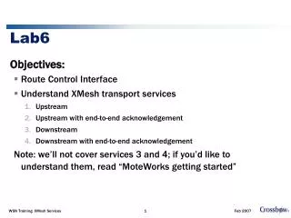
EECS150 Fall 2000 Lab6 - Nasty Realities by Sammy Sy. Don’t let the title scare you. Even though the final project might be nasty, this lab is not. Sections. Some information on the electrical components in this lab Capacitance vs Propagation delay Reflection and Termination

E N D
EECS150 Fall 2000Lab6 - Nasty Realitiesby Sammy Sy Don’t let the title scare you. Even though the final project might be nasty, this lab is not.
Sections • Some information on the electrical components in this lab • Capacitance vs Propagation delay • Reflection and Termination • Capacitive Coupling • Extra Xilinx tips
Figure 1a Breadboard connections Components (1) • Breadboard • Which holes are connected with which?
Figure 1b Ribbon cable DIP plug Components (2) • Ribbon cable • Is interference a problem? • We’ll find out
Components (3) • Resistors and capacitors • Time to figure out how those colors on resistors and numbers on capacitors mean • Detailed description on the lab handout • Example: red-black-brown = 200 ohm (red = 2, black = 0, brown 1)
Figure 2b 74F04PC hex inverter pinouts Components (4) • 74F04PC hex inverter chip • Essentially just a bunch of inverter gates • Remember an inverter requires input, and VCC and GND.
Components (5) • We also need a bunch of normal wires to hook them up • Remind yourself how to play with the pulse generator • More practice with the mighty oscilloscope
What to do in this lab • You will be building several simple circuits to measure gate delays, and observe how reflection and capacitance affect electrical signals. • The lab handout gives you the step-by-step procedures. • Some motivations.
Capacitance vs Propagation delay (1) • Capacitance is evil • Why? • It limits how fast a gate transition can take place. • In fact, all conductors are subject to this evilness - for example, two wires together.
Figure 2a 5-stage ring oscillator Capacitance vs Propagation delay (2) • Ring oscillator • No stable state • Therefore, those inverters will be switching as fast as their capacitance allows. • T = 2 * delay * N
Reflection and Termination (1) • What’s reflection? • If you view electrical signal as propagation of E&M waves, then a wire is no different than optical fiber. • When the signal hits a dead end, it bounces back and interferes with itself. • Can be solved by proper termination.
Reflection and Termination (2) • Terminate by eliminating those dead ends. • Add some load (i.e.: resistance). • I once heard that TV cable companies detect undesired “fanouts” by sending a strong pulse to the wire and count the number of reflections received. • Now you can outsmart them.
Capacitive Coupling (1) • Recall the ribbon cable • Signal on wire interferes with the neighboring wires. It’s especially noticeable in long and crowded wires. • An undriven wire is more easily affected.
Capacitive Coupling (2) • For example, say we have 3 wires A, B and C arranged linearly (i.e. B is between A and B). • Let A = some signal • Let B = undriven • Let C = some other signal • Because B is undriven, it’s easily influenced by A and C
Capacitive Coupling (3) • Simultaneously, B affects A and C. • We can introduce a “shield” to protect the signals in A and C. • If we ground B, it becomes much less likely to be manipulated by A and C. • Thus, A and C won’t step onto each others’ toes.
Xilinx Tips (1) • This lab doesn’t need Xilinx (relieved!) • Difference between FDC and FDR (similarly applies to CC8CE vs CC8RE, etc) • FDC = D-type flipflop with asynchronous clear • FDR = D-type flipflop with synchronous reset
Xilinx Tips (2) • Keep the clock signal clean! • Read the implementation log • Once you’ve made something into a macro, the original schematic file is not used by the project anymore. • Ground yourself