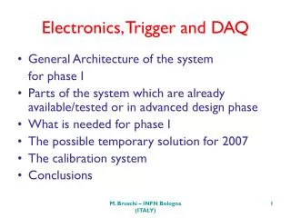
Electronics, Trigger and DAQ
Electronics, Trigger and DAQ. General Architecture of the system for phase I Parts of the system which are already available/tested or in advanced design phase What is needed for phase I The possible temporary solution for 2007 The calibration system Conclusions.

Electronics, Trigger and DAQ
E N D
Presentation Transcript
Electronics, Trigger and DAQ • General Architecture of the system for phase I • Parts of the system which are already available/tested or in advanced design phase • What is needed for phase I • The possible temporary solution for 2007 • The calibration system • Conclusions M. Bruschi – INFN Bologna (ITALY)
General Architecture of the system for phase I M. Bruschi – INFN Bologna (ITALY)
LUCID Readout Goals • The basic operation of the LUCID electronics is to count the track multiplicity per bunch crossing in the detector • The track multiplicity in a Cerenkov tube is proportional to the light signal collected by a photosensitive device (in our case PMT or MAPMT) • In the baseline readout scheme proposed for phase I the light produced in a single Cerenkov tube will be readout directly by a single PMT device and the amplitude and time of arrival of the signal will be used to count the detector track multiplicity. • In the second readout scheme the light produced in a single tube will be split in many (up to 16) groups of quartz fibers connected to a MAPMT placed in a moderately low radiation area (5 Gy/year at highest lumi). The LUCID information relevant to measure the luminosity of the experiment must be available: • in the global ATLAS triggered event • in the online monitor • to possibly form a trigger for interaction or high event multiplicity rejection. M. Bruschi – INFN Bologna (ITALY)
Readout Schemes for Phase I ~4m ~80-100 m LUCID Nose Sh. USA15 Shielded Tw. Pair coaxial LUCID +PMT PMT FED ROD TRIGGER 1) Quartz Fibers Shielded Tw. Pair/optical fibers MAMPT FED (MAROC) ROD TRIGGER 2) LUCID • Number of channels (per detector side): 16 PMT/ 1 MAPMT (4 ch.) • The front end has been conceived as having as least components as • possible for two reasons: • - short time to produce it (from April 2006) • - it is deployed in an area that during is not easily accessible M. Bruschi – INFN Bologna (ITALY)
Baseline Readout Scheme Description • Signals from PMT are fed into a PMT FED card (formed by a PMT mother card and PMT daughters cards both tested on Dec. 06) providing the necessary amplification. The differential output is sent to USA15 via twisted pair shielded cable • The received analog signal is processed by a ROD CARD. The multiplicity per tube is evaluated by LUT combining time of arrival and amplitude information. The result of the processing is stored in pipeline to be read pending a L1A and sent directly to the trigger card • The TRIGGER CARD processes the multiplicity from all the tubes and forms the LUCID trigger (interaction/high multiplicity rejection/ …). Online luminosity scalers are implemented in the logic and readout via VME. The processed data, stored in a pipeline, are sent to ROS pending a L1A and form part of the LUCID event. • The design of the TRIGGER CARD is already started since it must be used also in another project expected to run this year (R&D on a fast tracking trigger for silicon devices) • In case the ROD CARD were not available for the end of this year we propose a temporary readout solution for 2007 based on the TRIGGER CARD plus a VME based system. The online luminosity and trigger features would still be available while the system debugging would be performed via the VME QDC system (tested on Dec. 06) • The feature of time arrival of the event readout will be in this case added to the system tested on Dec. 06 by means of a Constant Fraction Discriminator (CFD) card already in the production phase and of a VME TDC module M. Bruschi – INFN Bologna (ITALY)
LUCID READOUT+TRIGGER (PHASE I) PMT FED 100 m USA 15 R O D PMT 1 ROS 100 m T R I G G E R C A R D PMT 16 TTCRQ VME IF OnLine LUMI 4 diff. TX lines R O D MAMPT FED (MAROC) MAMPT GOL LINK+TTCRQ 100 m HV, LV, SLOW CONTROL FED To LVL1 TTCRQ TTCRQ M. Bruschi – INFN Bologna (ITALY)
PMT DAUGHTER CARDS The FED CARDS In Out 1 2 3 16 PMT MOTHER CARD Amplifier+ Diff. Line Drivers PMT FED PMF: HV Divider Signal Routing MAROC chip MRO MAROC (ROMAN POTS): 4 SUM OVER 16 CHANNELS (ANALOG OUT) 64 THR. DISCRIMINATOR (DIGITAL OUT/GOL LINKS) MAPMT FED M. Bruschi – INFN Bologna (ITALY)
LUCID ROD CARD (2+2units ) – VME 9U s-LINK Busy ~200 Bytes/ev s-LINK to ROS 160 MB/s 6 Bytes EVENT BUFFER DPRAM stru 1 6 Bytes DPRAM Analog_In 1 stru 2 stru 2 Analog_In 2 from CTRL LOGIC from CTRL LOGIC 6 Bytes DPRAM stru 16 Analog_In 16 VME I.F GOL_In 1 GOL RX VME P1 GOL_In 2 GOL_In 10 3 LVDS S/P LVDS 1 (to trig. unit) 3 LVDS 2 (to trig. unit) LVDS 3 (to trig. unit) 3 LVDS 4 (to trig. unit) CTRL LOGIC opt. lnk from TTCEX TTCRQ i.f. M. Bruschi – INFN Bologna (ITALY)
Single Tube Readout Unit 1/4 data from the MRO GOL LINK #1 1 2 20 TUBE LUT (1 MB) LHC Clock Progr. GATE & DEL CFD (Prog. Thr +NR) #16 3 1 Fan Out to the trigger unit GI + ADC Multiplicity per Tube LUT 8 3 DIFF. ANALOG INPUT (FROM FED) ADC GATE STRU RAW DATA TO READOUT per STRU ~ 6 Bytes/BC 25 ns LHC Clock LHC Int. Time time Note: the dashed components are used only for the MAPMT readout scheme 20 ns 5 ns int reset ADC GATE M. Bruschi – INFN Bologna (ITALY)
LUCID TRIGGER CARD (1 unit ) – VME 9U s-LINK Busy s-LINK to ROS 160 MB/s ONLINE LUMINOSITY SCALERS LVDS 1 D e t e c t o r 1 ~40 Bytes/ev LVDS 2 Signal Buffer LVDS 3 LVDS 4 FPGA based TRIGGER PROCESSING UNIT LVDS 5 VME I.F 5 ser. Inp 60 bit/BC VME P1 5 ser. Inp 60 bit/BC LVDS 1 D e t e c t o r 2 LVDS 2 Signal Buffer LVDS 3 LVDS 4 FPGA: Algorithm Flexibility LVDS 5 CTRL LOGIC opt. lnk from TTCEX TTCRQ i.f. to the L1 trigger M. Bruschi – INFN Bologna (ITALY)
Scalers in the Trigger Card (Firmware) for Online Luminosity I. Collision/Zero Counting LUCID A LUCID C 1 3 16 tubes 4 2 II. Particle Counting • 4 x 3564 x 32bit ~ 60kB (1-4 x BCIDs x Scaler depth) 1 2 (If LUCID A-C Coincidence) • All scalers start/stop are • synchronized with the Orbit signal to • scale over the same interval at a BC • precision • Scalers are incremented on L1A (for • dead time correction) • Scalers read-out by VME and sent to • DCS (~ 120 kB for each Luminosity • Block –few min-) for processing, • to be published at any time 3 4 (If LUCID A-C Coincidence) • 4 x 3564 x 32bit ~ 60kB • III. Total Orbit Counter • For normalization (Average) • 32bit M. Bruschi – INFN Bologna (ITALY)
The LUCID Data Flow ATLAS TDAQ S-link ~200 Hz (~2 Hz) ROS… • Offline Luminosity • Luminosity data stream L1A ~100 kHz (~1 kHz) • CTP/LVL1 • Dead-time • Pre-scale • LVL2 + EF • Pre-scale LUCID LUCID Trigger (X Hz) (VME) SBC Cross checks with CTP Monitoring Online Lum. Scalers (Ethernet) LB (Ethernet) IS DCS • Run Control • Luminosity Block Analysis Control Room Conditions Database M. Bruschi – INFN Bologna (ITALY)
Parts of the system which are already available/tested or in advanced design phase M. Bruschi – INFN Bologna (ITALY)
2ch Preamp+Driver PMT Daughter Card The prototypePMT FED Test Board x5 x10 Mother Card ANALOG SIGNAL Outputs (18x4) PMT Inputs MAPMT MAPMT HV M. Bruschi – INFN Bologna (ITALY)
The prototype TX-RX System DEC. 06 Test DAQ TX system: PMT Mother Card + 36 Daughter Cards ATLAS TDAQ-01-06-01 RX system: VME RX card 8 channels PZ adj Gain adj SBC CORBO QDC ADC SCALER 7 VME RX cards x2÷4 Gain adj M. Bruschi – INFN Bologna (ITALY) PZ adj
Signal Characteristics Cable length=100 m Source: Pulser PMT: R2496 Cable length=100 m Source: Led pulses The pole-zero correction performed by the RX card to compensate for cable losses works properly M. Bruschi – INFN Bologna (ITALY)
The Electronics GainMeasured at the Dec. 06 Test Beam PMT 2 QDC CH 2 S= 28.7 N=0.56 100 m cable PMT 2 TX RX QDC CH 2 S= 345.2 N=6.7 GAIN=345.2/28.7~12 (S/N)=51.4 to be compared with 51.3 No S/N worsening observed Good linearity and uniformity of response M. Bruschi – INFN Bologna (ITALY)
TDAQ-01-06-01 at the DEC. 06 Test Beam During the December 2006 Test Beam we took data using the last version of TDAQ and the following VME modules: 1 SBC + Hard Drive (Standalone mode) 1 CORBO (Trigger and Busy) 2 CAEN QDC V792 1 CAEN SCALER 1 CAEN SEQUENCER V551 2 CAEN ADC V550 M. Bruschi – INFN Bologna (ITALY)
The CFD card • We are producing (the design is completed) a Constant Fraction Discriminator card which will be used: • to test the timing performances of the readout chain • as system block for the possible temporary solution in 2007 (see next) • Each VME 6U card will handle 8 channels ANALOG (TO QDC) LVDS (TO TDC) LVDS (TO TRIGGER CARD) NIM (AUXILIARY) CFD FROM VME RX CARD OUTPUT M. Bruschi – INFN Bologna (ITALY)
THE TRIGGER CARD (SLIM/LUCID) ALTERA STRATIX II EP2S130F1508 • We merged the need of two projects (SLIM/LUCID) in a unique Trigger Card (EDRO) • whose design is already started • The specific purpose of each project will be defined by the design of the Mezzanine • (input signals routing) and of the FPGAsfirmware M. Bruschi – INFN Bologna (ITALY)
What is Needed for phase I MRO *NOT DIFFICULT DESIGN. MOSTLY SIGNAL ROUTING M. Bruschi – INFN Bologna (ITALY)
The possible temporary solution for 2007(in case ROD card not available) 100 m FED USA 15 3 RX B O A R D S 3 CF D B O A R D S PMT 1 ROS VME QDC/TDC 100 m T R I G G E R C A R D PMT 16 VME IF OnLine LUMI 20 4 diff. TX lines FED MAROC MAMPT 100 m HV, LV, SLOW CONTROL 20 To LVL1 • INTEGRATED ON TDAQ • ONLINE SCALERS • DEBUGGING VIA VME • MAROC DIGITAL PART NOT AVAILABLE TTCRQ M. Bruschi – INFN Bologna (ITALY)
LED Calibration System - I • The readout chain gain will be measured using a calibration system based on LED light. • We tested already such a system during the past test beam • The small amount of channels to be tested will allow to use the simple manual method used during the test beam • An improved version (VME programmable system, fully automatic ) is under design M. Bruschi – INFN Bologna (ITALY)
LED Calibration System - II Amplitude: ~ 4 V (variable in 10 mV steps) Duration: ~ 20 ns LUCID TUBE Optical Fiber PULSER LED CARD PMT Trigger Output (to the DAQ trigger logic) Led amplitude adjusted to see the single photoelectron signal M. Bruschi – INFN Bologna (ITALY)
Conclusions • An intense work for design and debugging the electronics solutions for LUCID has been performed during the last year • Tests on important elements for the FED and DAQ system of phase I have been successfully performed during the last test beam on December • We are reasonably confident that the phase I detector can be run integrated in the ATLAS TDAQ starting from the end of this year providing valuable and unique information for the experiment online and offline luminosity determination M. Bruschi – INFN Bologna (ITALY)
Backup Slides M. Bruschi – INFN Bologna (ITALY)
Description of some of the building blocks of the readout electronics • OPERA MAROC CHIP • Adapted to LUCID needs from the RP design (ATLAS Orsay group) • Gated Integrator + ADC • 8 bit for the total sum should be enough • Contacts have been taken with the LHCb preshower group (Clermont) for adapting their GI+ADC solution • LOGIC • Mainly Based on LUT • IMPLEMENTED on FPGAs • Flexible and robust • ENGINEERING • Integration in standard VME 9U M. Bruschi – INFN Bologna (ITALY)
Fibers readout scheme description • The high radiation dose level around LUCID in phase II suggests the possibility to transmit the light collected by the Cerenkov tubes on rad. hard quartz fibers (typ. ~60 fibers/tube grouped in up to 16 readout channel) to the front end electronics sitting on a low level irradiated area (nose shielding, 5 Gy/year) • Charged tracks crossing the fibers at an angle off the fiber axis could produce unwanted light (background) • The signals affected by this kind of background can be rejected by examining the pattern of hit fibers (and not only the total amount of light collected by the fibers) • The front end chip developed by the ROMAN POT group (MAROC) to read MAPMT (8x8 matrix of readout channel) offers the possibility to produce, for each tube: • An analog signal proportional to the light produced in the cerenkov tube (this feature was added for LUCID) • A digital signal based on the fast discrimination of the single MAPMT readout channel (used to study the pattern of hit fibers) No event Signal event Background event M. Bruschi – INFN Bologna (ITALY)
The MAROC CHIP LUCID ANALOG LUCID SLOW CTRL LUCID DIGITAL The MAROC chip design (ROMAN POT) has been modified in order to group up to 16 channel (ANALOG SUM) M. Bruschi – INFN Bologna (ITALY)
LUCID FED (for MAPMT) M. Bruschi – INFN Bologna (ITALY)
LUCID FED (for MAPMT) • The FED will sit in an area • irradiated by 5 Gy/year atmax. • luminosity • Nevertheless, also for phase I, • all radiation tolerant components • have been used • (GOL, TTCrq, ELMB, voltage • regulators LHC4913, • FPGA Flash ACTEL APA and • CPLD Xilinx XC9500) • In the FPGAs, the Triple Module • Redundancy logic has been • implemented • All the cards are in production • except the analog one (BUT: • the basic analog circuit is already • produced and tested) • Prototype (with MAROC2) • ready in spring M. Bruschi – INFN Bologna (ITALY)
AVERAGE ANODE CURRENT DRAWN BY PMT IN PHASE I Total average current per tube: 8 mA M. Bruschi – INFN Bologna (ITALY)
AVERAGE ANODE CURRENT DRAWN BY MAPMT IN PHASE I 10 fiber/tube (40 channel/MAPMT) Total average current per tube: 1.6 mA M. Bruschi – INFN Bologna (ITALY)