Download
1 / 22
220 likes | 241 Vues
This document provides a review of the EMC electronics and trigger system, including details of the electronics components, energy resolution, and trigger timing. It also outlines the trigger plan for future testing and collaboration with other institutions.

E N D
EMC Electronics and Trigger Review and Trigger Plan Valerio Bocci INFN Roma EMC Electronics: INFN Roma,INFN Perugia Trigger: INFN Roma,INFN Perugia,INFN Roma 3,INFN Naples,INFN LNF
SuperB EMC • EMC Barrel : • 5760 CsI(Tl) Crystals EMC Forward = 4400 Lyso Crystals (176 modules)
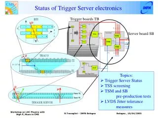
25 crystals tower readout electronics Crystals Mechanics X 5 4X X 5 X 5 Ranges Lvds 5 Shaper Range Board VFE Board Differential ADC Board 5 5 ranges analog Coded PIN Or APD ADC CLK I2c VME • 25 channel (full module readout) • All boards produced LNF General Meeting September 28, 2010 Valerio Bocci
Very Front End Board HV CSP Diff or SE DRV Buffer • EMC VFE Board • 5 CSP Channels • Enable to mount: Cremat,Hamamatsu,Home Made CSP • HV distribution CSP Buffer Diff or SE DRV CSP Buffer Diff or SE DRV CSP Buffer Diff or SE DRV CSP Buffer Diff or SE DRV LNF General Meeting September 28, 2010 Valerio Bocci
EMC Ranges shaper board X5 Channels Analog Rcv from FE x.5 CR200 Analog Diff Output Signal out 1bit range LVDS x32 CR200 ADC CLK Switch Logic Switch_Ctrl Cmp_stretch DAC Thr Setting ProAsic3 FPGA Range info Analog Coded Fast Comparator I2c LNF General Meeting September 28, 2010 Valerio Bocci
Energy Resolution new ADB Low Range High Range Elba SuperB General Meeting 30 May- 5 Jume Valerio Bocci
Old ADB Energy resolution LNF XI General Meeting December 1, 2009 Valerio Bocci
As we know the noise spectrum depends from the shaping time we do not find any noise source with an heavy contribution. Power Spectrum 500 ns Shaper Power Spectrum 250 ns Shaper Power Spectrum 100 ns Shaper More noise XV SuperB General Meeting – Caltech 14-17 December 2010 Valerio Bocci
We integrate the noise spectrum and we have evaluated the noise level in Veff • 100ns -> 745 uVeff(0.5-10.5 MHz) • 200 ns -> 565 uVeff (0.5-3.5 MHz) • 500 ns -> 418 uVeff (0.1-2.1 MHz ) XV SuperB General Meeting – Caltech 14-17 December 2010 Valerio Bocci
Electronics Plan • The electronics of the Forward follows the discussions of the detector and try to support the test beams. It is not fixed and strongly depends of the detector type. • After the SuperB approval we have to follow better the electronics of the Barrel where we have more fixed points. • We startup a collaboration with Roma3,Naples,LNF Perugia, for Central trigger design.
What we are doing for BTF 2 nd LNF Test • We want to study better the response of Crystals • The electronics worked well during the CERN test beams and we understood the noise source (shaper) • We don’t want to touch to much the electronics to have more or less the same system to factorize problems. • We only adjust the amplification chain to lower energy scale of the BTF (100 Mev to 500 Mev) Valerio Bocci 2011
2 nd BTF beam test High Gain 1MeV~12.6 mV 380 V OR Low Gain 193MeV = 1469 ADC 1MeV~3.77mV 308 V CSP CR110 4.3 V No Shaper attenuation Stage 1 Shaper preamp Stage 2*0.819 10x Shaper + driver Crystal ADC NC VFE VME RANGE Connect 1 CMS APD • We read one APD for channel • We use two scale High Gain Low Gain changing the APD voltage • Gain 0.6 mv/MeV (High Gain) 0.18 mv/Mev(Low Gain) Valerio Bocci 2011
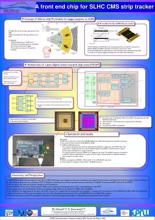
EMC Forward Trigger Primitives • SuperB EMC Forward = 4400 Lyso Crystals • 176 Sums unit Sum of the energy deposition of the 25 crystals of each Forward module. Elba SuperB General Meeting 30 May- 5 June Valerio Bocci
EMC Barrel Trigger Primitives • EMC Barrel :5760 CsI(Tl) Crystals • 480 Sums unit Sum of the energy deposition of 12 crystals of the barrel module any sample time Elba SuperB General Meeting 30 May- 5 June Valerio Bocci
EMC Fast Trigger Path and Slow Energy Path Energy Slow Path Double Range shaper Range (0,1) CSP X Ncryst Trigger Fast Path Analog S Pulse Encoder n LVDS Trigger Tower module Valerio Bocci 2011
EMC Forward tentative of Implementation Double Range shaper X5 Range CSP X5 X5 S 5 input VME Range Shaper 5 x 5 =25 crystal tower VFE New Circuit Analog Sum over 5 input. Analog S Pulse Encoder 5 input LVDS Trigger Tower module X 176 lvds Links Valerio Bocci 2011
Addr Addr Addr Addr Addr Addr Time Time Time Time Time Time Energy Energy Energy Energy Energy Energy EMC Trigger Processor 44x4=176 tower LVDS TP0_EMC Addr Ntower LVDS cables (176 Lvds cables Forward EMC) Active Towers Width DAQ • Trigger processor level0 • Cluser Information extracted • Addr of each tower • Extract Energy for each tower (width measurement) • Extract T for each Tower T Valerio Bocci 2011
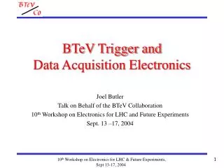
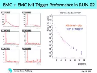
Trigger timing in the BaBarBarrel CsI (Tl doped) P. D. Dauncey et Al., “Design and performance of the level 1 calorimeter trigger for the BABAR detector” (2001) 3 thresholds applied to the signal of the tower. The plot shows the difference between the EMC trigger time and the DC trigger time. A FIR Filter with 8 parameters was applied to the signal. Its zero crossing occurred at roughly a fixed time distance from the start of the signal, it was used to gate the threshold information. Due to this mechanism the time resolution was about 100 ns.
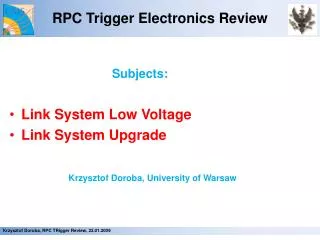
Trigger Crate TP0_EMC1 TP0_EMC2 TP0_FEMC TP0_EMC0 CTP TP0_DC0 TP0_DC0 Central Trigger Processor The central trigger processor get the informations from the TP0 units and create the trigger. The edge of DC chamber has the same addr structure of the EMC. Valerio Bocci 2011
Plan • For BTF FEMC test in May we need all the pieces for system integration asap. • We need a Babar Barrel CsI(Tl) to understand how to readout the Barrel • We setup a trigger group to define trigger strategy