Advancements in Nb3Sn Conductors for 15T Magnet Development at CERN
200 likes | 321 Vues
This document summarizes the rationale, research, and development efforts toward designing Nb3Sn-based 15T magnets at CERN. It highlights key specifications for the superconducting strands based on preliminary magnetic design and protection considerations. The performance results showcase significant improvements in critical current density (Jc) and stabilization techniques. Additionally, the studies address the relationship between Jc, residual resistivity ratio (RRR), and strand optimization, emphasizing the importance of careful material design in high-field magnet applications.

Advancements in Nb3Sn Conductors for 15T Magnet Development at CERN
E N D
Presentation Transcript
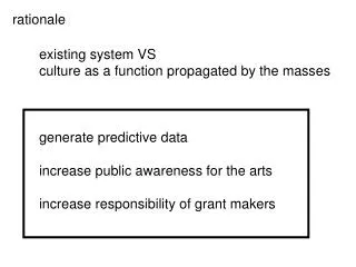
CERN-HFM conductors rationale L. Bottura With thanks to L. Oberli, Th. Boutboul, B. Bordini and “the crowd” in the Superconductors Laboratory Meeting on 11T dipole conductor CERN/FNAL October 4th, 2011
By courtesy of Th. Boutboul NED targets • The main goal of NED was to launch the R&D necessary to design and build a Nb3Sn based 15 T magnet • On basis of preliminary magnetic design and protection considerations, NED specifications for the strand were chosen: • Diameter1.250 mm • Eff. filament diameter < 50 µm • Cu-to-non-Cu ratio 1.25 ± 0.10 • Filament twist pitch 30 mm • non-Cu JC1500 A/mm2 @4.2 K & 15 T • minimum critical current 818 A at 15 T • RRR (after heat treatment) > 200 Very challenging specifications!
By courtesy of Th. Boutboul NED promises • PIT strand: Ic ~ 1400 A, Jc ~ 2500 A/mm2 (12 T) for 675 oC/84 h • Optimization launched at CERN. Results: 320 h @ 625 oC • 12 T and 4.2 K:Ic > 1500 A, Jc > 2700 A/mm2, + 10 %!! • 15 T and 4.2 K: Ic > 818 A(NED spec.), Jc ~ 1500 A/mm2
NED program results – 1/3 Jc of PIT wire produced within the scope of the NED R&D Best performance was achieved optimizing the heat treatment for low plateau temperature (625 °C) and long times (320 hrs) The production has gone through a technology transfer process clearly visible in the measured performance Clear improvement with present stable manufacturing conditions
NED program results – 2/3 Excellent RRR values at the beginning of the R&D, much degraded at later times Optimization of Jc leads to a marked decrease of RRR This has been traced to the presence of hot-spots in the strand
NED program results – 3/3 Modified strand architecture to improve the use of the real estate, and increase the optimization margin for JC at acceptable RRR For any given strand architecture based on react-able barriers there is an intrinsic limit in the maximum RRR achievable
By courtesy of B. Bordini Magneto-thermal stability
Magneto-thermal stability cook-book • Reduce the critical current of the strand to the minimum required for magnet performance (range of 2500 A/mm2, not much above) • Reduce the strand diameter (1 mm and smaller) and the diameter of the multi-filamentary region • Achieve a local RRR of the order of 100
By courtesy of B. Bordini Effect of RRR on stability – 1/4 0.8 mm 54/61 RRP® Nb3Sn strand Samples were prepared using the same strand (copper to non copper ratio ~ 0.92;effective filament size of ~ 80 μm) Heat treatment chosen in order to obtain different values of the RRR without significantly changing the critical current
By courtesy of B. Bordini Effect of RRR on stability – 2/4 ‘Perturbation region’: the quench current depends on the energy of the tiny perturbation acting on the strand (big variation of quench currents can occur) ‘Energy Region’: the quench current mainly depends on the potential energy stored in the current distribution V-H measurements at low fields shows that the minimum quench current significantly decrease by reducing the RRR below 100 4.2 K
By courtesy of B. Bordini Effect of RRR on stability – 3/4 At 1.9 K and with the same type of perturbation, the larger Jcand the smaller Cpof the wire (with respect to the values at 4.3 K) extend the ‘energy region’and move the ‘perturbation region’ towards higher magnetic fields. The semi-analytical model is in good agreement with the experimental data in the ‘energy region’ 1.9 K
By courtesy of B. Bordini Effect of RRR on stability – 4/4 The quench current at 4.3 K was computed for the minimum in the low field region (point C ) and for 12 T in the case of self-field instability and large perturbations (point B’). For RRR larger than 100, the instability at low field (in the case of the considered conductor) is not a problem for a magnet designed to work at 12 T (or larger fields). The high field instability does not improve much increasing the RRR above 100.
By courtesy of I. Pong and L. Oberli Strand center Fine grains Coarse grains Microstructure and real estate
A summary of what (we think) we understood • The initial NED specifications were possibly too demanding for stable performance in a magnet environment • There is an intrinsic interplay of critical current density, filament diameter, and RRR, equivalent to a critical surface for the overall performance of a given strand
1 1.5 2 2.5 3 3.5 4 200 150 100 50 Performance targets for Nb3Sn Performance Peak field Cost JC (kA/mm2) Target performance: Jc > 3 kA/mm2 Dfil < 20 m RRR > 100 PIT target Magnetization Field Quality Stability 10 20 50 100 RRP RRR (-) Dfil (m) Stability Protection
Present strand specifications (*) one of the main topics of the discussion today
Generic multipole (approximate integration in a coil of radius Rcoil): Case of sextupole in a dipole magnet: Scaled persistent current b3PC vs. strand M in dipoles for all SC synchrotrons to date Magnetization related matters
Expected field quality OST-RRP 54/61 • What is the actual field error ? • What can be tolerated and corrected ? M ≈ 500 mT M ≈ 200 mT b3 ≈ 300 units !!!
On-going strand work 0.7 mm, 108/127 stack RRP from OST 1 mm, 192 tubes PIT from Bruker EAS Work is on-going on a new strand architecture (169 stack) to reduce the filament diameter to 52 mm at 1 mm strand diameter, and 35 mm at 0.7 mm strand diameter R&D started for an alternative architecture with filaments of 30 mm at 0.7 mm strand diameter
Questions • Do we agree on specifications (strand, cable) for magnet R&D and magnet production ? • Material lead time is long (> 12 months), and we are already late. How do we manage/share the present stock ? • What is the procurement strategy beyond the magnet R&D ?