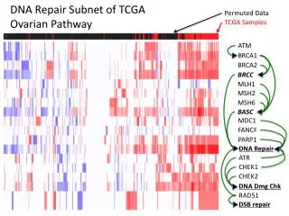
ATM
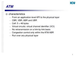
ATM. Topics. Introduction ATM Architecture Overview ATM Cell ATM Connections Addressing and Signaling ATM Layer Services IP over ATM. Introduction. Broadband Integrated Services Networks.

ATM
E N D
Presentation Transcript
Topics Introduction ATM Architecture Overview ATM Cell ATM Connections Addressing and Signaling ATM Layer Services IP over ATM
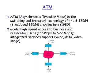
Broadband Integrated Services Networks • In the mid-1980s, the ITU-T (formerly CCITT) initiated a standardization effort to merge voice, video and data on a single network • The goal was to replace all existing networks (telephony networks, Cable TV network, data networks) with a single network infrastructure. The effort was called B-ISDN (Broadband Integrated Services Digital Networks) • The technology selected for B-ISDN was Asynchronous Transfer Mode (ATM) and SONET/SDH (Synchronous Optical Network/Synchronous Digital Hierarchy)
Traditional Network Infrastructure Telephone network Company B Company A Data network Video network Residential user x
B-ISDN BroadbandIntegrated Services Network (B-ISDN) Company B Company A Residential user x
ATM: The official definition • CCITT Definition (I.113, Section 2.2) • A transfer mode in which the information is organized into cells; it is asynchronous in the sense that the recurrence of cells containing information from a particular user is not necessarily periodic
Why “asynchronous”? Synchronous transfer mode (= Time division multiplexing) • Each source gets period assignment of bandwidth • good: fixed delays, no overhead • bad: poor utilization for bursty sources Asynchronous transfer mode (= Statistical multiplexing) • Sources packetize data. Packets are sent only if there is data • good: no bandwidth use when source is idle • bad: packet headers, buffering, multiplexing delay 1 2 3 4 1 2 3 4 1 2 3 4 1 2 3 4 1 2 3 4 1 2 3 4 1 2 3 4 H 1 H 3 H 3 H 2 H 1 H 4
ATM’s Key Concepts • ATM uses Virtual-Circuit Packet Switching • ATM can reserve capacity for a virtual circuit. This is useful for voice and video, which require a minimum level of service • Overhead for setting up a connection is expensive if data transmission is short (e.g., web browsing) • ATM packets are small and have a fixed sized • Packets in ATM are called cells • Small packets are good for voice and video transmissions Header(5 byte) Data (48 byte) Cell is 53 byte long
53 Byte Cells • Why 53 Bytes?A 48 byte payload was the result of a compromise between a 32 byte payload and a 64 byte payload • Advantages • Low packetization delay for continuous bit rate applications (video, audio) • Processing at switches is easier • Disadvantages • High overhead (5 Bytes per 48) • Poor utilization at lower line rates links
ATM Standardization • Until 1991, standardization occurred within CCITT (now: ITU-T) in a series of recommendations in the I series • In 1991, ATM Forum was formed as an industry consortium • ATM Forum starts to prepare specifications to accelerate the definition of ATM. • Specifications are passed to ITU-T for approval • Since 1993, ATM Forum drives the standardization process • IETF publishes Request for Comments (RFCs) that relate to IP/ATM issues
1985 1990 1995 2000 HFC networks Uses of ATM B-ISDN vision Internet vision ATM on the desktop Fast Ethernet IP-over- ATM MPLS (in core) ATM Enterprise backbones GigEthernet DOCSIS Special purpose applications with QoS demands Access Networks (xDSL)Frame Relay transport Voice trunking
The ATM Reference Model • ATM technology has its own protocol architecture Control Plane User Plane Upper Layer Upper Layer End-to-end layer ATM Adaptation Layer (AAL) Transfer of Cells ATM Layer Transmission of Bits Physical Layer
Layers of ATM Host A ATM Switch Host B
Function of the Layers Convergence AAL Segmentation and Reassembly Generic Flow Control Cell VPI/VCI translation Cell multiplexing and demultiplexing Cell header generation and extraction ATM HEC header sequence generation and verification Cell delineation Transmission frame generation and recovery TC Physical Bit timing Physical medium PM TC: transmission convergencePM Physical medium
ATM Layer • The ATM Layer is responsible for the transport of 53 byte cells across an ATM network • Multiplex logical channels within a physical channel
ATM Layer The ATM Layer can provide a variety of services for cells from an ATM virtual connection: • Constant Bit Rate (CBR) • guarantees a fixed capacity, similar to circuit switching • guarantees a maximum delay for cells • Variable Bit Rate (VBR) • guarantees an average throughput and maximum delay • Available Bit Rate (ABR) • guarantees ‘fairness” with respect to other traffic • Unspecified Bit Rate (UBR) • service is on a “best effort” basis • Guarantees Frame Rate (GFR) • Throughput guarantee for multiple cell frames
ATM Adaptation Layer (AAL) • AAL encapsulates user-level data • Performs segmentation and reassembly of user-level messages Data Data AAL AAL reassembly segmentation ATM Network Cells Cells
ATM Cells • 4-bit Generic flow control • 8/12 bit Virtual Path Identifier • 16 bit Virtual Channel Identifier • 3 bit Payload Type • 1 bit Cell Loss Priority • 8 bit Header Error Control • 48 byte payload • GFC field only in UNI cells UNI Cell
ATM Cells • 4-bit Generic flow control • 8/12 bit Virtual Path Identifier • 16 bit Virtual Channel Identifier • 3 bit Payload Type • 1 bit Cell Loss Priority • 8 bit Header Error Control • 48 byte payload • At NNI: GFC byte is used for additional VPI NNI Cell
A Packet Switch Header Data Packet Packet switch
Forwarding with VCs Part 1: VC setup from X to E
Forwarding with VCs Part 2: Forwarding the packet 2 5 5 3
Virtual Paths and Virtual Circuits Link Virtual ChannelConnection Virtual Path Connections VPI identifies virtual path (8 or 12 bits) VCI identifies virtual channel in a virtual path (16 bits)
VPI/VCI assignment at ATM switches 1/24 3/24 7/24 2/17 3/24 1/40
ATM Endsystem Addresses (AESA) • All ATM addresses are 20 bytes long • Source and destination address are supplied when setting up a connection • ATM endpoints use the NSAP (Network Service Access Point) format from ISO OSI • Three different types of addresses • NSAP encoding for E.164: ISDN telephone numbers (e.g., 001-434-9822200) • DCC format: for public networks • ICD format: for private networks
ATM Endsystem Addresses (AESA) AFI (1 byte): Authority and Format IdentifierTells which addressing scheme to use IDI (2-8 bytes): Initial Domain IdentifierIdentifies a domain within scope of addressing authority HO-DSP (4-10 bytes): High-order bits of domain specific partsimilar to network prefix of IP address ESI (6 bytes): Endsystem identifiersimilar to host number of IP address SEL (1 byte): Selectorfor endsystem use only
Formats of an ATM address AFI: Authority and Format Identifier DCC: Data Country Code ICD: International Code Designator E.164: ISDN (telephone) Number IDI: Initial Domain Identifier DSP: Domain Specific Part ESI: Endsystem identifier SEL: Selector
Example: Default Assignment of ATM addresses by Cisco Systems 47.00918100000001604799FD01.0050A219F03B.0 ATM switch endsystem
Which Address Format To Use? • Currently each service provider makes its own choice • This introduces problems (SVC compatibility) • Most ATM switches support multiple formats • ATM Forum prepares standards to translate addresses at network boundaries (NNI interfaces) • Interworking of ATM Networks (IAN)
ATM UNI Signaling • Significant Signaling Protocols • ATM Forum: • UNI 3.0. UNI signaling protocol for point-to-point connections. • UNI 3.1. Supports point-to-multipoint connections. • UNI 4.0. Supports Leaf initiated join multipoint connections • PNNI. for network node signaling • The ATM Forum signaling specifications are based on the Q.2931 public network signaling protocol developed by the ITU-T. • specifies a call control message format • message type (setup, call proceeding, release) • Addresses • AAL parameters • Quality of Service (QoS)
Basic Signaling Exchange: Setup of a SVC ATM A B Setup to B Setup to B Call Proceeding Call Proceeding Connect Connect Connect ACK Connect ACK
Basic Signaling Exchange: Tear down ATM A B Release Release Release complete Release complete
ATM Services at the ATM Layer The following ATM services have been defined: Constant Bit Rate (CBR) Real-time Variable Bit Rate (rt-VBR) Non-real-time Variable Bit Rate (nrt-VBR) Available Bit Rate (ABR) Unspecified Bit Rate (UBR) Guaranteed Frame Rate (GFR) ABR and UBR Usage of capacity VBR CBR Time
ATM Network Services • CDVT characterizes an interface and is not connection specific • PCR in UBR is not subject to CAC or UPC
Constant Bit Rate (CBR) • For applications with constant rate requirements: video and audio • Very sensitive to delay and delay variations • Adaptation Layer: AAL1 rate peak rate time
Variable Bit Rate (rt-VBR, nrt-VBR) • For applications with variable rate requirements: compressed audio and video (rt-VBR)data applications (nrt-VBR), such as transactions • Adaptation Layer: AAL2, AAL 3 /4, AAL5 • Example: 30 sec MPEG-1 trace (from Terminator) • Peak rate: 1.9 Mbps • Avg. rate: 0.261 Mbps
Available Bit Rate (ABR) • For applications that can tolerate changes to rateInterconnection of LANs • Transmission rate (ACR) changes between MCR and PCR • ACR is set by a feedback algorithm (to be discussed) • Adaptation Layer: AAL 5 PCR ACR MCR time
Unspecified Bit Rate (UBR) • “Best effort service” • No bandwidth, loss, or delay guarantees • UBR gets the bandwidth that is not used by CBR, VBR, ABR • No UPC and no feedback • Applications: Non-critical data applications (file transfer, web access, etc.) • Adaptation Layer: AAL5
Guaranteed Frame Rate (UBR) • For non-real-time applications which guarantee a minimum rate guarantee • Recognizes AAL5 boundaries • Frame consists of multiple cells • If a cell is dropped, remaining cells from that frame will be dropped as well • Minimum rate (MCR) is guaranteed by network, the rest (up to PCR) is delivered on a best effort basis. • Adaptation Layer: AAL5
UDP TCP Classical IP over ATM • ATM network card is treated like an Ethernet card • ATM Network consists of multiple logical subnets • IP datagram is encapsulated and then passed to AAL5 IP SNAP / 802.2 LLC AAL 5 ATM Layer Physical Layer
Logical IP Subnetwork (LIS) • Each host has a VC to the ATMARP server • ATMARP translates between IP and ATM addresses • Each host connects to another host on the same LIS with a dedicated VC • IP datagrams to hosts on a different subnet are sent to router
Problem with Classical IP-over-ATM • ATMARP server only resolve addresses for a single LIS • Traffic from A to B goes through two IP routers, even though both hosts are on the same ATM network