Download
1 / 33
330 likes | 357 Vues
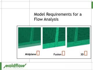
Midplane . Fusion . 3D . Model Requirements for a Flow Analysis. Introduction. Aim Understand the requirements of a good mesh for midplane, Fusion and 3D Why do it A good mesh is critical for accurate results Get better models from CAD when requirements are understood

E N D
Midplane Fusion 3D Model Requirements for a Flow Analysis
Introduction • Aim • Understand the requirements of a good mesh for midplane, Fusion and 3D • Why do it • A good mesh is critical for accurate results • Get better models from CAD when requirements are understood • Easier translation • Overview • General mesh requirements • 3D specific requirements
Mesh Types & Model Requirements • Often same requirements for different mesh types • Fusion • 3D • Most of the time 3D models are built from Fusion meshes • Must have good Fusion model to create 3D model • Midplane • Some requirements specific to the mesh type
Free Edges • Edge of an element that does not touch another element • Fusion & 3D • Must not have any free edges • Midplane • Will occur at partedges
Non-Manifold Edges • Edge where 3 or more elements share the edge • A “T” intersection • Fusion & 3D • Must NOT have any non-manifold edges • Midplane • Will have non-manifold edgesat all rib intersections
Unmatched Matched Match Ratio – Fusion Only • An element on one side of wall thickness matched to another element on the other side of the wall • Fusion • Poor match relates to poor thickness determination • Should be least 85% for Flow, 90% for Warp
1 3 Matched but not reciprocally matched Reciprocally Matched 2 4 1 3 2 4 Reciprocal Match Ratio – Fusion Only • When two elements on opposite walls are matched with each other • 100% reciprocal match is when all matched elements are reciprocally matched • Should be over 90% reciprocal match • For good warpage results Nodes do not have to be aligned to be reciprocally matched
h L Aspect Ratio • Ratio of Length to Height of an element • Fusion & Midplane • Average < 3:1 • Maximum < 6:1 • Higher can be tolerated for flow analysis, • High ratios cause problems with cool and warp • 3D • Maximum 30:1 on Fusion mesh to be converted • Tetrahedral mesh ratio < 50:1 is best
Connectivity Regions • A group of elements that are connected together • All mesh types must have one connectivity region for the part • Mesh statistics will report more than one region if cooling geometry is in the study
Element Orientation • Define the “Top” positive normal side and “Bottom” side of elements • Fusion • Must have the Top (Blue) side pointing outward • Midplane • Orientation should be consistent • 3D • Not applicable Two elements not correct
Intersecting Elements • Intersections • Elements intersect the plane of other elements • Shown in Red • Fusion & 3D & Midplane • Must not have any
Overlapping Elements • Overlaps • Elements in the sameplane intersect (takethe same space) • Shown in Blue • Fusion & 3D & Midplane • Must not have any
Zero Area Elements • Zero Area Element • Very low volume or edge length • Normally caused by very high aspect ratio elements • Fusion & 3D & Midplane • Must not have any
Thickness Representation • Ensure the thickness of the model is correct • “Chunky” geometry • Fusion will not calculate the thickness correctly • Must be represented by a 3D model
TH 10x TH 4x TH 2x TH Chunky Geometry • Less than 4:1 width : thickness ratio • Prefer a ratio of greater than 10:1 • Heat Transfer only done on faces (blue) not in thickness direction (Green) • 2:1 ratio - thickness is 33% of the perimeter • 4:1 ratio - thickness is 20% of the perimeter • 10:1 ratio - thickness is 9% of the perimeter
1 2 Correct Inverted Node 1 and 2 on the same side of the face shared by the two elements 3D only – Inverted Elements • Must not have inverted elements
3D only - Number of Element Layers • Default number of rows 6 • Used for most applications • 8 rows better for 3D fiber orientation • As number of rows increases so does the aspect ratio • This can lead to problems with Navier-Stokes solver
3D Only • Collapsed faces • A node is defined on two opposing faces • Local zero thickness • Must not have • Internal long edges • Edge length of element inside part to the edge length on the part surface • Should be <2.5:1
3D Only • Extremely large volumes • Ratio of volume of element to the average • Should be under 20:1 • High aspect ratios • Maximum aspect ratio should be < 50:1 • Small angle between faces • Node close to the plane formed by the plane of the other elements • Should be > 2 degrees Normal Small angle
2.0 mm 2.0 mm 1.0 mm 1.0 mm 3.0 mm 3.0 mm Mesh Density Effects - Hesitation • To pick up hesitation, three rows of elements across a major change in thickness are required
Mesh Density Effects - Weld Lines • The mesh at the weld line location must be dense enough to pick up the weld line
Nominal wall 2.5 mm Thin Region 1.25 mm Mesh Density Effects - Air Traps • Air traps may not be predicted if the mesh is not fine enough in thin regions
Mesh Detail • Model must represent FLOW characteristics • Thickness • Flow length • Volume • Small features of a part should be eliminated from a flow model • Blends • Radii • Fillets
Effect of Geometry on Fill Pressure • Thickness • Greatest effect on pressure • Flow length • Second greatest effect • Volume • Virtually no effect
1.0 mm 1.5 mm R 0.25 mm Effect of Corner Radii • Fusion & Midplane • No effect on pressure • Purple dots are nodes • To represent radii, small node spacing is required • Creates high aspect ratio for very minor thickness changes • 3D • Can see local effect of corner radii but must have very high mesh density
A Model With and Without Radii • No Radii 14 elements > 6:1 aspect ratio • With Radii 561 elements >6:1 aspect ratio No Radii With Radii
Shear Rate (3D) [1/sec] A Model With and Without Radii • 3D can pick up local high shear at sharp corners • Requires very fine mesh • Only has local affect
Compute Time, Mesh Density and Accuracy • As mesh density increases • The compute time increases exponentially • Limited accuracy improvement Material, ABS 1.9 mm nominal wall Processing Cond. 60-235-1 Computer 2.8 GHz, 1 Gig Ram