SEM TEM in Polymer Characterization
Scanning Electron Microscopy (SEM)UsesSample PreparationInstrumentPrinciplesMicrographsTransmission Electron Microscopy (TEM)UsesSample PreparationInstrumentPrinciplesMicrographs. Outline. TopographyTexture/surface of a sampleMorphologySize, shape, order of particlesCompositionElem

SEM TEM in Polymer Characterization
E N D
Presentation Transcript
1. SEM & TEM in Polymer Characterization EMAC 403
Matt Fullana
2. Scanning Electron Microscopy (SEM)
Uses
Sample Preparation
Instrument
Principles
Micrographs
Transmission Electron Microscopy (TEM)
Uses
Sample Preparation
Instrument
Principles
Micrographs
Outline
3. Topography
Texture/surface of a sample
Morphology
Size, shape, order of particles
Composition
Elemental composition of sample
Crystalline Structure
Arrangement present within sample What can you see with an SEM?
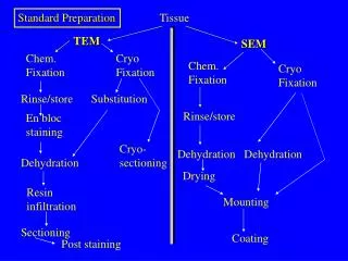
4. Samples must be small enough to fit in sample chamber
Most modern microscopes can safely accommodate samples up to 15cm in height
Samples must be electrically conductive
Polymer samples typically need to be sputter coated to make sample conductive
Ultra-thin metal coating
Usually gold or gold/palladium alloy
Coating helps to improve image resolution SEM Sample Preparation
5. Once sample is properly prepared, it is placed inside the sample chamber
Once chamber is under vacuum, a high voltage is placed across a tungsten filament to generate a beam of high energy electrons (electron gun) and serves as the cathode
The position of the anode allows for the generated electrons to accelerate downward towards the sample
Condensing lenses �condense� the electrons into a beam and objective lenses focus the beam to a fine point on the sample Scanning Electron Microscopy
6. Scanning Electron Microscopy
7. Scanning coils move the focused beam across the sample in a raster scan pattern
Same principle used in televisions
Scan speed is controllable Scanning Electron Microscopy
8. As electron beam strikes sample, secondary electrons are emitted from the sample
In addition, backscattered electrons are also emitted from the sample Scanning Electron Microscopy
9. SEM Sample Interactions
10.
Secondary Electrons
Back-Scattered Electrons SEM Signals / Detectors
11. Electrons strike the sample surface
As a result, some electrons �splash� out from the sample (secondary electrons)
A detector with a strong positive charge attracts these electrons, however depending on the surface topography, not all electrons will be attracted
Electrons on high �peaks� will be attracted to the positively charged detector
Electrons in low �valleys� will not be attracted to the detector
Secondary Electron Detector
12. SEM Micrographs
13. SEM Micrographs
14. Electrons from high-energy beam strike the sample
Some electrons pass close to a nucleus and are deflected by the positive charge
These back-scattered electrons return to the sample surface moving at high speed
Back-scattered electrons is dependent on atomic number of sample
Can provide elemental composition information about a sample Back-Scattered Electron Detector
15. Back-Scattered Electron Detector
16. Morphology
Shape, size, order of particles in sample
Crystalline Structure
Arrangement of atoms in the sample
Imperfections in crystalline structure (defects)
Composition
Elemental composition of the sample What can we see with a TEM?
17. Samples need to be extremely thin to be electron transparent so electron beam can penetrate
Ultramicrotomy is a method used for slicing samples
Slices need to be 50-100nm thick for effective TEM analysis with good resolution
TEM Sample Preparation
18. Instrument setup is similar to SEM
Instead of employing a raster scan across the sample surface, the electron beam is �transmitted� through the sample
Material density determines darkening of micrograph
Darker areas on micrograph indicate a denser packing of atoms which correlates to less electrons reaching the fluorescent screen
Electrons which penetrate the sample are collected on a screen/detector and converted into an image Transmission Electron Microscopy
19. Transmission Electron Microscopy
20. TEM Micrographs
21. TEM Micrographs
22. TEM Micrographs
23. Pros
Easier sample preparation
Ability to image larger samples
Ability to view a larger sample area SEM Pros and Cons
24. Pros
Higher magnifications are possible (50,000,000x)
Resolution is higher (below 0.5�)
Possible to image individual atoms
TEM Pros and Cons
25. Questions?