Download
1 / 21
210 likes | 229 Vues
This presentation discusses the status and analysis of the Helical FOFO channel of alternating solenoids for ionization cooling in a 6D space, covering simulations, stability, efficiency, and future plans.

E N D
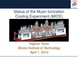
Status of HFOFO Snake for 6D Ionization Cooling Y. Alexahin (FNAL APC) Nomenclature: HFOFO = Helical FOFO channel of alternating solenoids (ASOL) FOFO-xyz = FOFO with xyz resonance phase advance per focusing cell consisting of one solenoid + all other stuff (RF cavities etc.) Talk outline: HFOFO-60 (6 cell period, Q1) - G4BL simulations HFOFO-120 (6 cell period, Q2) - smaller beta @ absorbers Really low-beta FOFO: FOFO-180 (2 cell period, Q1) HFOFO-270 (4 cell period, Q3) Plans 3rd Muon Collider Design Workshop, BNL, December 1-3, 2009
Basic Idea of HFOFO (6 Cell Example) 2 alternating solenoids absorbers RF cavities • The idea: create rotating B field by periodically tilting solenoids, e.g. with 6-solenoid period. • Periodic orbits for μ+ and μ- look exactly the same, just shifted by a half period (3 solenoids). • With tune Q>1 (per period) rD>0 muons with higher momentum make a longer path longitudinal cooling achieved even with planar absorbers B [T] Bx50 Bz By50 z [cm] y x, y [cm] y x x z [cm] Periodic orbit for p=200MeV/c In the subsequent plots all values in cm HFOFO Status - Y. Alexahin 3rd MCDW BNL December 2, 2009
Beta-functions & tunes (200MHz HFOFO-60) 3 x y Solenoids: L=24cm, Rin=60cm, Rout=92cm, pitch 7mrad, Bzmax=2.35T (p=200MeV/c) RF: 200 MHz pillbox 2x36cm, Emax=16MV/m Absorbers: 15cm LH2 planar at the absorber locations < > ~ 70cm - compare with MICE’s < > ~ 45cm The best results with 7mrad pitch angle, no absorber wedge angle: mode I II III tune 1.239+0.012i 1.279+0.007i 0.181+0.002i _eq (mm) 3.2 4.5 6.9 ImQ=0.007 cooling rate d log / dz = 22/L ImQ = 1/70m Bmax=2.3T j=58A/mm^2, Itot=4.4MA/solenoid There was a difficulty in equalization of damping rates of the transverse modes HFOFO Status - Y. Alexahin 3rd MCDW BNL December 2, 2009
Tune “repulsion” from integer resonance 4 no absorber, no RF QI, II Nice surprise: Large 2nd order chromaticity due to nonlinear field components keeps both tunes from crossing the integer ! p/200 orbit length/L0 Momentum compaction factor: - in contrast to classical HCC with homogeneous absorber where to ensure longitudinal damping. p/200 HFOFO Status - Y. Alexahin 3rd MCDW BNL December 2, 2009
Excursion - Longitudinal Hamiltonian 5 K URF =0.007 =0.014 p p -0 (rad) Kinetic energy in quasi-static approximation Contour plot of the longitudinal Hamiltonian for =0.014 - kinematic nonlinearity limits momentum acceptance, not insufficient RF bucket depth. where = orbit length/L0 Longitudinal separatrix reaches maximum at 0.007 It seems I underestimated URF by a factor of 2 RF phase angle can be increased from the present 27 faster cooling! HFOFO Status - Y. Alexahin 3rd MCDW BNL December 2, 2009
Tracking with G4BL 6 (p-p0)/p0 px/p0 py/p0 x [cm] t [ns] y [cm] Stochastic processes on, but no decays mechanical momenta, p0=200MeV/c blue - initial (the same ensemble), red – after 20 periods (122m) HFOFO Status - Y. Alexahin 3rd MCDW BNL December 2, 2009
Analysis of G4BL Tracking Data 7 N/N0 no decays! With decays transmission over 20 periods (122.4m) is > 85% Initial/final N [cm]=1.7, 1.8, 2.1 / 0.37, 0.7, 1.1 6D cooling efficiency (following R.Palmer’s definition) Q6 20 G4BL stochs. off MICCD G4BL stochs. on Transmission vs period # N [cm] Recipe for emittance calculation: compute normal mode amplitudes am for each muon using lattice eigenvectors subtract average values find distribution in action variables Jm =| am |2 fit with exponential function 3N 2N 1N Normal mode emittances (normalized) vs period # (_eq = 0.32, 0.45, 0.69) multiply m by 00 HFOFO Status - Y. Alexahin 3rd MCDW BNL December 2, 2009
Damping Rate Equalization with Quadrupole Field 8 y (cm) Dy (cm) Dx (cm) z x (cm) z Most efficient “equalizer” is constant quadrupole field superimposed on the main solenidal field. With a gradient of just 0.057 T/m: mode I II III tune 1.240+0.0088i 1.286+0.0087i 0.178+0.0036i _eq (mm) 3.9 3.8 4.7 (w/o quad was 3.2 4.5 6.9) The sum of betas smaller - no increase in transverse emittance (despite smaller long. emittance) 50% stronger long. damping due to larger dispersion (smaller solenoid pitch required) The effect does not depend on quad tilt (and polarity) as well as on the muon sign - the channel is still good for both! The quadrupole field does not have to be constant along the axis: it is high-beta region in solenoids that is most effective HFOFO Status - Y. Alexahin 3rd MCDW BNL December 2, 2009
G4BL Simulations with Quad “Equalizer” 9 N/N0 with quad 3N 1N with quad w/o quad 2N period # period # w/o quad 3N 2N 1N The ratio of 6D emittances and the cooling efficiency remain the same with quad on period # HFOFO Status - Y. Alexahin 3rd MCDW BNL December 2, 2009
Absorber Container and RF Cavity Windows 10 A MODERN AIRCRAFT ALUMINUM ALLOY (thanks to Don Summers) Aluminum Alloy Yield Tensile Radiation Name Composition Density Strength Strength Length % by weight g/cc ksi ksi cm 300K 300K 20K 6061-T6 1.0Mg .6Si .3Cu .2Cr 2.70 40 45 68 8.86 2090-T81 2.7Cu 2.2Li .12Zr 2.59 74 82 120 9.18 Supposedly 2090-T81 windows can be made 0.1mm thick (as compared to 0.18mm of 6061-T6 in MICE). Three cases considered below: No container nor cavity windows (original lattice) Two 0.1mm 2090-T81 container windows per absorber, no safety nor cavity windows Two 0.1mm 2090-T81 container windows per absorber + three 0.38mm Be windows per two RF cavities Q1 Q2 Q31N (mm) 2N (mm) 3N (mm) ERF (MV/m) No windows 1.239+0.012i 1.279+0.007i 0.181+0.0025i 3.2 4.5 6.9 16.0 Abs. winds 1.241+0.012i 1.281+0.007i 0.185+0.0026i 3.7 5.1 7.5 16.3 + RF winds 1.243+0.013i 1.286+0.007i 0.191+0.0033i 4.0 5.8 7.3 17.5 Though the effect of the windows is tolerable (<30% increase in the equilibrium emittance) it would be worth while to look for a lighter material for the absorber windows (Be?, LiH??) HFOFO Status - Y. Alexahin 3rd MCDW BNL December 2, 2009
G4BL Simulations with Walls 11 3N 2N 1N period # no quad! N/N0 w/o windows with windows period # Final emittances for the cases 1 and 3: 1N (mm) 2N (mm) 3N (mm) 6D (mm^3) No windows 3.67 7.01 10.96 218.2 With all windows 3.63 7.77 10.22 212.9 - Strange result, may be due to a faster cooling with 9% increase in losses and the RF gradient HFOFO Status - Y. Alexahin 3rd MCDW BNL December 2, 2009
HFOFO-60 Summary 12 HFOFO snake with resonant dispersion generation allows to obtain large dispersion (~0.5m in the considered 200MHz case) and achieve 6D cooling even with planar absorbers. HFOFO snake can simultaneously cool both μ+ and μ- . Despite being resonant, the 200MHz HFOFO snake has sufficiently large momentum acceptance and transverse dynamic aperture to accept beam from Dave’s bunching / rotation section (G4BL simulations are in the pipeline) Additional quadrupole field (~constant along the axis) equalizes transverse damping rates without compromising cooling efficiency. HFOFO with 200MHz twin RF cavities gives T < 6mm, L ~10mm By reducing solenoid sizes and using single-cell RF the transverse emittance can be reduced to T ~ 3mm, while keeping L ~10mm HFOFO characteristics can be further improved (dedicated effort is needed) Absorber and RF windows do not strongly affect 200MHz HFOFO performance, however, their effect on subsequent stages of 6D cooling (especially the effect of the absorber windows) will be very detrimental; studies of Be or LiH usage as the window material are necessary. If the answer is positive, one can project T ~ 1.5mm, L ~2.5mm for 800MHz HFOFO-60° channel HFOFO Status - Y. Alexahin 3rd MCDW BNL December 2, 2009
HFOFO-120° 13 Channel parameters (6-cell period, Q=2): RF: 800 MHz pillbox RF 2x8cm, Emax=32MV/m Solenoids: L=8cm, Rin=16cm, Rout=26cm, Inclination 3mrad in rotated planes: 0, /3, 2/3, , 4/3, 5/3. Absorbers: LiH, total width (on-axis) 1.2cm, full wedge angle 0.2rad Total length of 6-cell period 1.68m With p0=150MeV/c BLS=94.5T Bzmax=11.5T x y Bz/BLS Dx Dy Bx/BLS By/BLS x x HFOFO Status - Y. Alexahin 3rd MCDW BNL December 2, 2009
HFOFO-120° 14 Q2 Q1 p/p0 p/p0 – 1 With constant quadrupole field of just 1.45 T/m and no RF windows mode I II III tune 2.272+0.0052i 2.313+0.0053i 0.215+0.0029i _eq (mm) 0.83 0.78 0.80 HFOFO-120° channel with LiH absorbers provides ~ the same emittance as HFOFO-60° with LH2. No problem with absorber windows but more sensitive to outer RF windows due to larger beta there ( open cell on one side?) Momentum acceptance looks O.K., no tracking simulations performed yet but no problem expected 800 MHz HFOFO-120° channel with LH2 absorber (if problem with windows solved) can give T ~ 0.5mm, L ~0.5mm HFOFO Status - Y. Alexahin 3rd MCDW BNL December 2, 2009
FOFO snake for final 6D cooling 15 Bz (T) 10*By Phase advance >180/cell small -function at absorber smaller emittance. With ~ half-integer tunes PIC? Simplest structure – just two solenoids: Q1, Q2 =0.007 p/100 z orbit lengthening x,y [cm] p/100 - no 2nd order chromaticity, - momentum compaction too small and of the wrong sign! z HFOFO Status - Y. Alexahin 3rd MCDW BNL December 2, 2009
Helical snake for final 6D cooling 16 By increasing B-field strength it is possible to get phase advance >180/cell and small -function at the solenoid center much smaller emittance. Tune/period > odd_integer for resonant orbit excitation Puzzle: 2-cell period (planar snake), Q>1 6-cell period, Q>3 4-cell period, Q>3 6-cell period, Q>5 HFOFO-270° channel parameters (4-cell period): 800 MHz pillbox RF 2x8cm, Emax=32MV/m Solenoids: L=8cm, Rin=16cm, Rout=26cm, Inclination: vertical +3mrad, horizontal +3mrad, vertical -3mrad, horizontal -3mrad Absorbers: LiH, width (on-axis) 1.5cm, no wedge angle Total length of 4-cell period 1.12m Bzmax=18.5 T for p0=100MeV/c p < 0 significant over-focusing required p > 0 1 2 4 3 HFOFO Status - Y. Alexahin 3rd MCDW BNL December 2, 2009
HFOFO-270° 17 y x x,y [cm] Dy Dx - very small reduction in min at the price of significant increase in Bzmax With constant quadrupole field of gradient 3.25T/m mode I II III tune 3.315+0.0083i 3.211+0.0085i 0.149+0.0025i _eq (mm) 0.27 0.24 0.76 HFOFO Status - Y. Alexahin 3rd MCDW BNL December 2, 2009
HFOFO-270° Momentum Acceptance 18 Q1 Q2 Static momentum acceptance is fine: (-9%,+19%), but the dynamic acceptance is just 16% (full width) – barely enough to accommodate the equilibrium momentum spread. To increase dynamic acceptance one can: - reduce solenoid pitch angle (to reduce p) - reduce p0 (to increase 1/2) Both these methods are bad for longitudinal cooling – Careful optimization is necessary No tracking simulations yet, problems with transmission expected p/p0 p/p0 – 1 HFOFO Status - Y. Alexahin 3rd MCDW BNL December 2, 2009
Return to FOFO-180° 19 Since there is no clear gain in going to 270° (just problems), more effort was applied to find solution for 180°. A superposed dipole field generated by additional coils can do the job. Such a field can not be obtained by displacing solenoids: Bz / BLS y x By / BLS Dy Dx Bzmax=15.5 T for p0=100MeV/c - within the reach of Nb3Sn technology HFOFO Status - Y. Alexahin 3rd MCDW BNL December 2, 2009
FOFO-180° Momentum Acceptance 20 Q1 - 1 Q2 - 1 p/p0 p/p0 – 1 _min [cm] This design is not finished yet Search for a helical configuration is underway Emittances well below 0.5mm can be expected p/p0 HFOFO Status - Y. Alexahin 3rd MCDW BNL December 2, 2009
Plans 21 Search for the final stage HFOFO configuration (by IPAC10) Front end with HFOFO (by April 2010 IDS meeting) Determination of the number of stages and configuration for each stage (by the next MCDW) Optimization of each stage parameters (2010-2012) End-to-end simulation with matching between the stages (by 2012) HFOFO Status - Y. Alexahin 3rd MCDW BNL December 2, 2009