Download
1 / 36
370 likes | 529 Vues
MICE : The Muon Ionization Cooling Experiment. Linda R. Coney Muon Collider Conference – 29 June 2011. Outline. Introduction MICE Description Step 1 Results Cooling Channel Status Conclusions. Neutrino Factory and Muon Collider R&D. Neutrino Factory. Challenges:

E N D
MICE: The Muon Ionization Cooling Experiment Linda R. Coney Muon Collider Conference – 29 June 2011
Outline • Introduction • MICE Description • Step 1 Results • Cooling Channel Status • Conclusions
Neutrino Factory and Muon Collider R&D Neutrino Factory • Challenges: • Intense proton driver • Complex target • Accelerate muon beams • From pion decay • Large phase space g ie. High emittance g Need to cool beam • What do we need? • MICE • Proof of ionization cooling • Target studies (MERIT) • RF in magnetic field (MUCOOL) Introduction MICE Step 1 Cooling Channel Conclusions
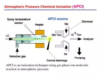
Muon Cooling • Reduction in normalized emittance (without scraping) is needed for efficient m beam acceleration & luminosity • Conventional beam cooling techniques require relatively long time (muon lifetime 2 ms) • A new solution is required… • Ionization Cooling • Energy loss by ionization (dE/dX) • Lose momentum in all dimensions • Restore longitudinal with forward re-acceleration by RF cavities Cooling is achieved best for low Z material -> Liquid Hydrogen Introduction MICE Step 1 Cooling Channel Conclusions
MICE: Muon Ionization Cooling Experiment • MICE Goals: • Design, build, commission and operate a realistic section of cooling channel • Measure its performance in a variety of modes of operation and beam conditions… … results will be used to optimize Neutrino Factory and Muon Collider designs. Spectrometer Solenoid & Tracker RFCC Module LH2 Absorber Introduction MICE Step 1 Cooling Channel Conclusions
MICE: Design & Goals • MICE is designed to produce a 10% cooling effect on the muon beam • Use particle detectors to measure the cooling effect to ~1% • Measurements done using muon beams with momentum 140 – 240 MeV/c and different selected emittances • Method: • Create beam of muons • Identify muons and reject background • Measure single particle parameters x, px, y, py, pz • Cool muons in absorber • Restore longitudinal momentum component with RF cavities • Identify outgoing particles to reject electrons from muon decay Introduction MICE Step 1 Cooling Channel Conclusions
MICE: International Involvement Institutions worldwide contributing to the demonstration of muon ionization cooling at MICE Introduction MICE Step 1 Cooling Channel Conclusions
Commission beam line & detectors Precisely measure incoming emittance & compare trackers Precisely measure muon cooling Test sustainable cooling Operate full cooling channel MICE: Steps • Step 1 is now complete g Step IV in 2012 Introduction MICE Step 1 Cooling Channel Conclusions
MICE Description • Located at the ISIS 800 MeV proton synchrotron at Rutherford Appleton Laboratory Introduction MICE Step 1 Cooling Channel Conclusions
MICE: Step 1 Beam Line • Produce p from p interactions with a titanium target • Transport p (Q123) and select momentum (D1) • Collect m (DS) and select momentum (D2) • Transport m to MICE and match to cooling channel • Maximize m purity (reduce p contamination) • Maximize transmission • Define optics for the MICE program LM Introduction MICE Step 1 Cooling Channel Conclusions
MICE: Beam Line • Target, Q123, D1 inside ISIS synchrotron enclosure • Decay Solenoid, Q456, TOF0, CKOVa/b inside DSA • Q789, TOF1, TOF2, KL, EMR in MICE Hall Introduction MICE Step 1 Cooling Channel Conclusions
MICE target path ISIS cycles MS marker ISIS losses MICE: Target • Titanium cylinder • installed in ISIS August 2009 • Target is working beautifully • Target stability checked every 10,000 pulses • Monitoring target behavior & timing • Dips into beam with ~90g acceleration • Target Operation: • 570,000 pulses to date in ISIS • Offline target ran 2 M actuations • Have online & offline working targets • T2.8 is a live spare for ISIS target Introduction MICE Step 1 Cooling Channel Conclusions
Downstream PID: reject decay electrons Time of Flight – TOF2(Italy/Bulgaria) Kloe-Light Calorimeter – KL(Italy) Electron-Muon Ranger – EMR(UGeneva) Upstream PID: discriminate between p, p, m Beam Profile Monitors(FNAL) Threshold Cerenkovs(UMiss/Belgium) Time of Flight – TOF0 & TOF1(Italy/Bulgaria) MICE: Particle Identification Detectors Introduction MICE Step 1 Cooling Channel Conclusions
MICE: Trackers & Diffuser • Trackers before/after cooling channel • Inside 4 T solenoid magnet (US) • Measures x, x’, y, y’, Pz • 5 stations/tracker, 3 planes/station (U/V/W) • 350 mm scintillating fiber doublet layers • Performance: • Light yield goal: 10 PE g measured 11.2 & 10.7 • Measured track residual 650 mm with 470 mm point resolution • Efficiency 99.8% and 99.6% (<0.2% dead ch) • Diffuser (Oxford) • Enable study of cooling over a range of emittance • Integral part of Step II & beyond • At upstream end of tracker 1 • 4 stacked variable thickness disks • Camera iris design Introduction MICE Step 1 Cooling Channel Conclusions
MICE: Absorber - AFC • Absorber-Focusing Coil – AFC • LH2 absorbers inside Absorber-Focus-Coil (AFC) module with superconducting coils to provide strong focus for muon cooling • 3 modules by Step VI • LH2 Absorber (KEK) • 20.7 liters LH2 • 35 cm long on beam axis • 15 cm radius • Focusing Coils (UK) • 2 coils • 26.3 cm inner radius • 4 T in solenoid mode Introduction MICE Step 1 Cooling Channel Conclusions
MICE: RF - RFCC • RF Coupling Coil – RFCC • Provides magnetic field to guide muons through cooling cell • Cavities restore longitudinal momentum after absorbers • RF Cavities(LBNL) • 4 cavities/module • Normal conducting 201.25 MHz • 8 MV/m • Curved Be windows(UMiss) • Coupling Coil (China/LBNL) • Single coil - 7.8 T • Cooled by cryocoolers • RF power • ~1MW in 1ms pulse at 1HZ/cavity • 4 sets of amplifiers(LBNL,CERN)being refurbished at Daresbury Lab(UK, UMiss – NSF)
Outline Reminder • Introduction • MICE Description • Step 1 Data-Taking • Commission beam line and detectors • Cooling Channel Status • Conclusions Introduction MICE Step 1 Cooling Channel Conclusions
Beam at the end of the Decay Solenoid D2 tuning Step 1: Creating the Muon Beam • Need good m purity • Use interplay between D1-D2 • Tune D1 to fix p-peak • Tune D2 to select downstream momentum fraction • Select backward-going m at D2 • p/m ratio for 238±24 MeV/c < 2% M.Apollonio Imperial • Defining a beam line: magnet current rescaling by momentum • Choose p or electron beam for calibration Introduction MICE Step 1 Cooling Channel Conclusions
Step 1: Defining Muon Beam Optics • MICE will need m beam with variable momentum (140-240 MeV/c) and emittance (3-10 mm) • Matrix of 9 optics points is defined • Start at hydrogen absorber • Find a,b,t at upstream face of diffuser g energy loss • Determine momentum at upstream face of diffuser • Define 9 initial (M0) muon beam configurations • Baseline beam is (6-200) Introduction MICE Step 1 Cooling Channel Conclusions
Step 1: Data-Taking • Goals • Calibrate beam line detectors • Luminosity Monitor, Beam Profile Monitors • TOF0, TOF1, TOF2, CKOVs, KL • Understand the beam • Composition • Rates • Momentum scale • First phase-space reconstruction • Take data for each point in (e-p) matrix • MICE beam designed to be tunable • Understand beam parameters for each configuration • Compare data to beam line model • Prepare for Steps with cooling • Successful 2 month data-taking summer 2010 Meant to be done using precise spectrometer g Necessary to improvise Introduction MICE Step 1 Cooling Channel Conclusions
Q1 Q2 Q5 Q7 Q3 Q4 Q6 Q8 Q9 decay solenoid LumiMon GVA1 TOF0 BPM2 TOF1 TOF2 Proton absorber Step 1: Data D1 D2 Machine Physics [15/6, 16/6] 2010 • Beam line configuration with detectors used for analysis ISIS User Run - Summer 2010 Machine Physics [13/8, 15/8] 2010 • Beam Rate vs Tgt depth studies • max. beam loss: 4V • Over 340000 target actuations / 11M triggers • upstream triplet scan • dipoles scan & decay solenoid scan • downstream triplets scan • downstream single quadrupole scan • beam composition studies • optics data-taking: (e,p) matrix • DAQ & Controls systems tests • On Line Monitoring • Beam Rate vs Tgt depth studies • max beam loss: 10V maximize m production while operating in a parasitic mode Introduction MICE Step 1 Cooling Channel Conclusions
0.40 m 0.42 m TOF0 10 x 4cm scintillator bars sx = 1.15 cm 7 x 6cm bars sx = 1.73 cm TOF1 Step 1: TOF Commissioning • Two planes of 1 inch thick orthogonal scintillator slabs in x and y • Timing information & beam profile data • 2D grid provides spatial information • Used to Calculate Optical Parameters [The design and commissioning of the MICE upstream time-of-flight system, R. Bertoni et al. , NIM-A 615 (2010) 14-26] Introduction MICE Step 1 Cooling Channel Conclusions
Step 1: Analyses • Particle Rate vs. Losses in ISIS • Maximize m rate – want hundreds/spill • Beam Composition • First emittance measurement in MICE • Target operation studies • Depth, delay, acceleration • Proton absorber • Eliminate protons in m+ beam • Data quality • daily reference runs to verify stability Introduction MICE Step 1 Analyses Cooling Channel Conclusions
Step 1 Analyses: Particle Rate Studies • Want 100s of muons/spill • Systematically study particle rates in MICE vs ISIS beam loss • Used p and m+/- beams m- beam 3.2 ms gate m+ beam A. Dobbs IC London • Linear relationship over beam loss range of ~0.5 – 4.7 V • Typical run conditions at 2V: • 11 m-/spill • ~60 m+/spill 1 ms gate A. Dobbs IC London Introduction MICE Step 1 Analyses Cooling Channel Conclusions
TOF0 TOF1 Step 1 Analyses: First e Measurement • For each particle: know time-of-flight and position (x,y) at each detector • Momentum-dependent transfer matrices map particle motion from TOF0 to TOF1 through drifts and quad triplet • G4MICE used to simulate beam, determine energy loss along path, and estimate detector effects • Estimate initial path length and momentum • Using transfer map: • Iterate and improve calculation of path length and momentum • Calculate initial and final momentum at TOF0 and TOF1 • Determine phase space of beam at TOF planes, x,y, px, py Use TOF0 and TOF1 particle detectors to determine phase space parameters of the muon beam (x0,y0) (x1,y1) Introduction MICE Step 1 Analyses Cooling Channel Conclusions
backward m e p g m forward m e p calibration p gm,p,e e Measurement: Particle Timing • Timing information used for both particle ID and position measurement (x,y) at TOF0 and TOF1 • Selection of good muon • Identified using time-of-flight measurement with 71 ps resolution (6-200) Baseline MICE muon beam setting Pion beam for detector calibration (also contains e and m) Introduction MICE Step 1 Analyses Cooling Channel Conclusions
Measurement: TOF Position • Transverse Position Determination with TOF detectors • Start with size of slab crossing (4x4cm, 6x6cm) • Use difference in arrival time of signals at PMTs in each slab to improve position measurement • Calibration corrected for time walk and cable lengths • sx ~ 1.0 cm • Beam profiles in TOF0 • Position using only slab width (left) and position determined by using signal arrival time in PMTs (right) TOF0 Introduction MICE Step 1 Analyses Cooling Channel Conclusions
e Measurement Result: Data vs MC • Good muon, position, momentum, emittance calculated • Reconstructed transverse phase space of the baseline MICE beam (6-200) at TOF1 y (mm) vs x (mm) x (mrad) vs x (mm) y (mrad) vs y (mm) Data MC M.Rayner OxfordU Introduction MICE Step 1 Analyses Cooling Channel Conclusions
Step 1: Data-Taking • Goals • Calibrate beam line detectors • Luminosity Monitor, Beam Profile Monitors • TOF0, TOF1, TOF2, CKOVs, KL • Understand the beam • Composition • Rates • Momentum scale • First phase-space reconstruction • Take data for each point in (e-p) matrix • MICE beam designed to be tunable • Understand beam parameters for each configuration • Compare data to beam line model • Prepare for Steps with cooling • Muon beams produced routinely Introduction MICE Step 1 Cooling Channel Conclusions
Beyond Step 1: MICE Cooling Channel Introduction MICE Step 1 Cooling Channel Conclusions
Status: Cooling Channel Components • Tracker (US, UK, Japan) • Both trackers ready, tested with cosmic rays • Resolution, Light Yield & Efficiency exceed design goals • Currently improving firmware, integrating with MICE DAQ, enhancing LED calibration system • NIM paper out soon • Spectrometer Solenoids (US) • Trackers sit inside solenoids • 4 T superconducting • 5 coils: 1 main tracker coil • 2 end coils, 2 matching coils • In depth studies done and modifications underway • Reassembly and test this year • Next Steps require spectrometers for precise emittance measurements Introduction MICE Step 1 Cooling Channel Conclusions
Status: Cooling Channel Components • Step IV requires absorber for first cooling measurements • First LH2 absorber now at RAL • Absorber Focus Coils • First coil has been wound in UK • Test program under development • First magnet g RAL December • Solid absorbers • LiH disk finished • LiH wedges in production (2 x 45°) • Test emittance exchange • Maybe Al, C, polyethylene Introduction MICE Step 1 Cooling Channel Conclusions
Status: Cooling Channel Components • Step V requires RFCC module for replenishing longitudinal component of momentum • RF Cavities • Provides magnetic field to guide muons through cooling cell • Restore longitudinal momentum after absorbers • All cavities have been made – tuners being fabricated – testing proceeding well • RF Coupling Coils • Fabrication in progress Introduction MICE Step 1 Cooling Channel Conclusions
MICE: Preparation for Next Steps • LH2 Delivery System • Infrastructure progressing well – vent system, pipe/valve & gas panel installation • Test cryostat is in Hall & cold, making LHe - test first with He then LH2 • EMR • 6 layers of detector installed in Hall – Running cosmics – beam data starts next week – July ISIS User Run – EMR test run • RF Power • Planning of power layout in progress • Refurbishing 2 RF amplifiers at Daresbury – one complete Introduction MICE Step 1 Cooling Channel Conclusions
MICE: Conclusions • MICE data-taking for Step 1 is complete • Innovative method used to make first measurements of beam emittance using time-of-flight detectors • MICE muon beam is understood and ready for the arrival of the cooling channel Introduction MICE Step 1 Cooling Channel Conclusions
m MICE in Action