Animal Tracking Status (ORNL)
270 likes | 475 Vues
Animal Tracking Status (ORNL). Recent ORNL Animal Tracking Progress/Challenges. Tracking Hardware System architecture Camera changes Animal burrow Illumination adjustments/experiments Calibration tools Tracking software Improved image acquisition code

Animal Tracking Status (ORNL)
E N D
Presentation Transcript
Recent ORNL Animal Tracking Progress/Challenges • Tracking Hardware • System architecture • Camera changes • Animal burrow • Illumination adjustments/experiments • Calibration tools • Tracking software • Improved image acquisition code • Improved camera calibration routine • Enhanced segmentation • Faster pose measurement • Phantom tracking/SPECT study • Animal studies
System Architecture SPECT Gantry with Optical Tracking Motion Control PC System Clock SPECT Data Acquisition PC Time-Stamped Gantry Position File Time-Stamped SPECT Event Files Optical Tracking PC Time-Stamped Pose File
Tracking/SPECT Gantry Calibration Phantom IR Strobe Mounts CMOS Cameras SPECT Detectors
Stereo Camera System Imrpovements • Adjusted the vertical view angle from 0 degrees to 10-15 degrees above SPECT gantry rotation axis. • Moved cameras closer together in the horizontal plane (30-degrees) to improve view between SPECT detectors. • Firmware updated to allow hardware trigger. 30-degrees
Animal Burrow- Reflection Elimination • Why are reflections a problem? See image on bottom-right. • Contracted with Deposition Sciences Inc. (DSI) to apply AR coating on the exterior and interior surfaces to eliminate reflections. • DSI claimed to have a low pressure chemical vapor deposition (LPCVD) method that would get coating up into the inside end of tube. • Glass tubes returned, and reflections from the outside surface were eliminated. • Reflections from inside surface of glass are still present: little or no AR coating on the inside end of the tube. Animal within burrow LED reflection merged with marker
Illumination Adjustments • Built a trigger circuit to allow the IR LEDs to be strobed • Increased short-term power to LEDs • Freezes motion • Polarization experiments for reflection suppression: • Linear polarization of light source • Laser illumination • Cross-polarization filter on camera • Circular polarizing reflectors
Polarization Experiments for Reflection Elimination w/out polarization with polarization Coherent, polarized source(red laser) Retro reflector (diffuses polarization) Cross-polarization filter on camera Eliminates reflection Requires IR laser illumination Requires higher power laser to cover animal burrow Polarized IR LED light source Retro reflector (preserves polarization) Polarization filter on camera Eliminates reflection from opposite source Does not eliminate direct reflection Polarized white light source Reflector sheet rotates polarization Cross-polarization filter on camera Eliminates reflection Need spherical IR reflectors that rotate polarization
Calibration Tools • Camera Calibration Tool for: intrinsic (focal length, lens distortion) and extrinsic (camera-to-camera) calibration • Checkerboard target mounted to a plate INSIDE glass tube • Plate is adjustable using a “joystick” mounted to back of plate • Optical Tracking and SPECT Coordinate System Alignment Tool • Optical tracking coordinates relative to optical axis of camera #1 • SPECT coordinates relative to gantry axis-of-rotation • Tool contains: • Retro-reflective markers for optical system • Co-located Co-57 sources for SPECT system Stereo camera calibration tool Pin-hole collimator optical-to-SPECT coordinate calibration tool
Optical Tracking Software Progress • Changed acquisition code to acquire true simultaneous images with strobe using hardware trigger • Added MATLAB camera calibration routine with more sophisticated optimization (for intrinsic and extrinsic calibration) • Segmentation improvements: • threshold for seed points now software adjustable (new) • region growing • contour analysis • filtering based on correspondence (derived from fundamental matrix, F) (new) • filter on size/aspect-ratio (new) • centroid calculation • Least squares optimization for closest epipolar line that matches each pair of corresponding centroid points • Speed improvements by writing more efficient code (from 9 meas/sec to 15 meas/sec)
I-125 3-Rod Phantom Tracking/SPECT Study • Three capillaries filled with liquid I-125 were mounted to the inside of a plastic tube. • Retro reflectors were mounted to the outside of the tube. • The tube was fixed to a 6 degree-of-freedom translation mount. • Two ~1.5 hour SPECT scans were performed: • Scan 1: the phantom was translated axially 4 times, 2.0 mm per step • Scan 2: the phantom was translated laterally 4 time, 2.5 mm per step • Parallel- and pin-hole SPECT data were acquired for each scan. 3-rod phantom in plastic tube Translation mount
I-125 3-Rod Phantom Tracking/SPECT Study Movies of parallel-hole SPECT projections Axial Motion Lateral Motion
I-125 3-Rod Phantom Tracking/SPECT Study Plot of Measured (blue) vs. Actual (black dotted) Motion of Phantom 2.8 mm Axial Motion (2mm per step) Lateral Motion (2.5 mm per step) SPECT event data, pose data and timestamp data being analyzed by our JLAB partners for pose-corrected reconstruction software development.
Awake Animal Tracking Study • Balb/c mouse anesthetized using ketamine/xylazene. • Retro reflective markers placed on head of animal. • Animal allowed to wake up, then placed within the animal burrow on the SPECT gantry for tracking. • Animal was tracked for about 20 minutes. • Successful measurement of animal’s 3D position was accomplished ~99% of the total time.
Awake Animal Tracking Study (cont) • Animal preferred to be within the burrow towards the closed end. • Motion was primarily constrained to lateral and vertical (nodding) motion of the head. • Tracking system was able to stay “locked” onto the motion 99% of the time.
Animal Tracking Study (cont) Live video of computer screen showing stereo camera views and real-time segmentation/correspondence measurements (green) Camera 1 View Camera 2 View
Next Step: Awake Animal Tracking with Simultaneous SPECT Data Acquisition • We have recently put in place all hardware/software and protocols necessary to acquire SPECT data of animals in motion: • Robust awake animal tracking • New camera configuration • More robust/faster pose measurement software • Strobed illumination • Partial reflection elimination • Animal handling protocols • Experience with animal behavior • Optical Tracking/SPECT coordinate system calibration tools • We can now begin acquiring SPECT data with motion: • Additional phantom studies (point sources, line sources) • Awake animal studies
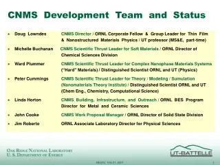
SPECT Reconstruction Algorithm Development Status for Static & Dynamic Animal Studies
Reconstruction Tools • We have created a suite of reconstruction tools for use in static animal SPECT studies: • 2D Filtered Backprojection • Parallel-hole • 3D ML-EM (w/ J. Gregor, Univ. of TN) • Parallel- and Pin-hole • 3D OS-EM (w/ J. Gregor, Univ. of TN) • Non-overlapping ordered subsets • Parallel and Pin-hole • A new data merging tool has been developed to serve as a platform for dynamic animal SPECT studies: • Time-Stamped SPECT Events • Time-Stamped Gantry Position Data • Time-Stamped Pose Measurements
Reconstruction Comparisons on Phantom with 3 Capillary Tubes (I-125) Trans-axial Slices FBP (Parallel-hole) OS-EM (Parallel-hole) OS-EM (Pin-hole)
Reconstruction Comparisons on Phantom with 3 Capillary Tubes (I-125) Volume Renderings FBP (Parallel-hole) OS-EM (Parallel-hole) OS-EM (Pin-hole)
Reconstruction Software Architecture Time-Stamped Gantry Position File Time-Stamped SPECT Event Files “Static” Tomographic Data File “DataMerger” (ORNL) Compressed Events “GAM” file FBP, ML-EM, OSEM Reconstruction (Static) Time-Stamped Pose File Event Remapping (JLAB) Pose-corrected SPECT Events Static SPECT images Pose-Corrected Reconstruction (JLAB) Pose-corrected SPECT images