Download

1 / 11
160 likes | 778 Vues
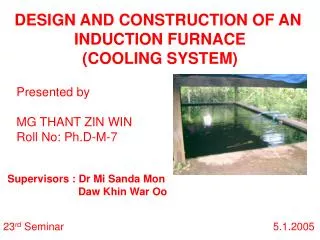
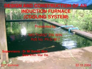
DESIGN AND CONSTRUCTION OF AN INDUCTION FURNACE (COOLING SYSTEM). Presented by MG THANT ZIN WIN Roll No: Ph.D-M-7. Supervisors : Dr Mi Sanda Mon Daw Khin War Oo. 21th Seminar 24.11.2004.

E N D
DESIGN AND CONSTRUCTION OF AN INDUCTION FURNACE(COOLING SYSTEM) Presented by MG THANT ZIN WIN Roll No: Ph.D-M-7 Supervisors : Dr Mi Sanda Mon Daw Khin War Oo 21th Seminar 24.11.2004
Evaporative Cooling System • Cooling Pond System • Spray Pond System • Cooling Tower System • Forced-draft cooling tower • Natural-draft cooling tower
Cooling Ponds • Satisfactory method of removing heat from water • Availability in large ground areas • Small investment by pushing up an earth dike 1.8 to 3.1 m (6 to 10 ft) high • Involving four principal heat transfer process _ Heat loss : evaporation, convection, radiation Heat gain : solar radiation, water supply
Mainly Consideration in Cooling Ponds • Required pond area: it depends on the number of degrees of cooling required and the net heat loss from each square foot of pond surface. • Equilibrium temperature: it is designed as E, at which heat loss would equal heat gain, is greatly affected by the amount of solar radiation, which is usually not known very accurately and which varies through the day.
Fig – Nomograph of cooling-pond preformance [Langhaar, Chem. Eng., 60(8), 194 (1953).]
where, D1 & D2 = the approaches to equilibrium for the entering and leaving water, ºF Vw = the wind velocity, mi/h PQ = the area of the pond surface, ft2/(gal.min) of flow to the pond The P factor assumes a pond with uniform flow, with turbulence, and with the water warmer than the air.
For Example : Determine the required size of a cooling pond operating at the following conditions. • Relative humidity, percent = 50 • Wind velocity, mi/h = 5 • Dry-bulb air temperature, ºF = 68 • Solar heat gain, Btu/(h.ft2) = 100 • Water quantity, gal/min = 10,000 • Water inlet temperature, ºF = 110 • Water outlet temperature, ºF = 90
Calculation By using the nomograph, P = 68, Q = 1.07 Required Area, A = PQ = 73 ft2/(gal.min) Area for 10,000 gal/min = 730,000 ft2 If we use a depth of 5 ft of pond, total volume of the pond would amount to a 45.5 - h holdup, which is more than the 24 - h holdup required to maintain a fairly constant discharge temperature throughout the day.
Table : Maximum Expected Solar Radiation at Various North Latitudes Source - [Langhaar, Chem. Eng., 60(8), 194 (1953).]