Download
1 / 5
50 likes | 196 Vues
Cooling system of the LHC b VE rtex LO cator. Overview of VELO system Current design of cooling system requirements, environment principle of mixed-phase CO 2 cooling system layout Discussion. towards spectrometer. Z. 80 [cm]. r. 0. f. -20. 0 8 45 mm.

E N D
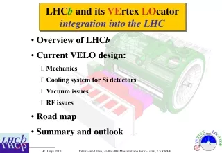
Cooling system of the LHCbVErtex LOcator • Overview of VELO system • Current design of cooling system • requirements, environment • principle of mixed-phase CO2 cooling system • layout • Discussion
towards spectrometer Z 80 [cm] r 0 f -20 0 8 45 mm LHCb Si Vertex Locator Modules etc. r|f f|r r|f • 300 mm thick Si single-side n-on-n • Design work ongoing for front-end chip • (DMILL and subm technologies) • total of 220 k channels, analogue, S/N=15 • one module: r and f measuring planes • with stereo angle • small overlap between opposite halves • for alignment and acceptance • cool down: -25 < Toperate < +10 oC • come as close as possible to LHC beams • minimise material between vertex and • first hit on Si put detectors in vacuum • large outgas rates of detector components • separate detectors from LHC vacuum retract by 3 cm during beam filling/tuning detector prototype
Detector module FEE power input: 128 channels/chip 16 chips/sensor 2 sensors/module 50 modules 204’800 channels at 6 mW/channel 1.2 kW from chips + radiation 0.3 kW Mock-up for thermal tests silicon sensor FE chip cooling interface
VELO mechanical design (v5.0) • Decouple access to silicon detectors • from access to primary vacuum • Baking up to 150 oC is possible • Use ultrapure neon venting • VELO and NEGs need not be rebaked • after access to Si detector Openings for feedthrough flanges (22’000 pins) Vertex detector half 120 cm 25 cm RF/Vacuum thin shield Exit window 1.5-2 mm thick Al Cooled Si sensors in secondary vacuum
Mixed-phase CO2 Cooling system Phase diagram CO2 • Advantages: • Radiation hard (used in nuclear power plants) • Non toxic (conc. < 5%), non flammable • Low pressure drop in microchannel tubes • Good thermodynamic properties • Widely available at low cost • No need to recover or recycle • Principle of operation: • CO2 is used in a two-phase cooling system. • The coolant is supplied as a liquid, the heat is taken away by evaporation. • LHCb VELO: in total, ~ 54 40 W of heat, each cooled by a pipe of OD=1.1/ID=0.9 mm. • Tested at NIKHEF: See LHCb 99-046/VELO • capacity of cooling pipe > 50 W • heat transfer coefficient between pipe and coolant > 2 W cm-2 K-1 critical point 100 solid liquid gas Pressure [bar] 10 vapor triple point 1 -80 -70 -60 -50 -40 -30 -20 -10 0 10 20 30 40 50 Temperature [°C]