Overview of Control System Design
Overview of Control System Design


Overview of Control System Design
E N D
Presentation Transcript
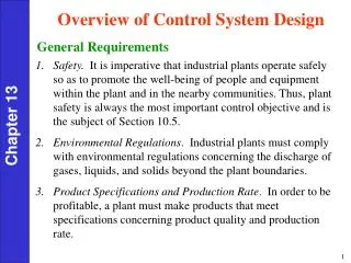
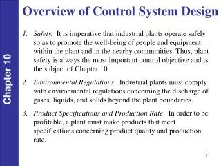
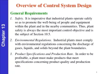
Overview of Control System Design • Safety. It is imperative that industrial plants operate safely so as to promote the well-being of people and equipment within the plant and in the nearby communities. Thus, plant safety is always the most important control objective and is the subject of Section 10.5. • Environmental Regulations. Industrial plants must comply with environmental regulations concerning the discharge of gases, liquids, and solids beyond the plant boundaries. • Product Specifications and Production Rate. In order to be profitable, a plant must make products that meet specifications concerning product quality and production rate. Chapter 10
Economic Plant Operation. It is an economic reality that the plant operation over long periods of time must be profitable. Thus, the control objectives must be consistent with the economic objectives. • Stable Plant Operation. The control system should facilitate smooth, stable plant operation without excessive oscillation in key process variables. Thus, it is desirable to have smooth, rapid set-point changes and rapid recovery from plant disturbances such as changes in feed composition. Chapter 10
Operator’s View of Process Control A Day in the Life of a Plant Operator
Operator’s View of Process Control • Pump A pumping oil has tripped - Cause Unknown • You switch to Pump B. That also trips - Cause Unknown • Soon hundreds of alarms are going off – Cause(s) Unknown • With in minutes you have an explosion and a fire. Two people are killed and a few hurt at this point. • It is 10:00 in the night. • The plant manager is in Aberdeen, Scotland, and not available. • You are on top of an off-shore oil platform in the middle of the North Sea. You are the Shift Supervisor: What do you do?
Process Safety is a Major Concern: The BIG Ones • Piper Alpha Disaster, Occidental Petroleum Scotland, 1988 • Off-shore oil platform explosion • 164 people killed • $2 Billion in losses • Union Carbide, Bhopal, India, 1984 • MIC release into atmosphere • 3000-10,000 people killed • 100,000 injured • $0.5-1.0 Billion in losses
BP Texas City Accident Video(short version) http://www.youtube.com/profile?user=USCSB#p/u/20/c9JY3eT4cdM
BP Texas City Accident Video(more detailed) http://www.csb.gov/investigations/detail.aspx?SID=20&Type=2&pg=1&F_All=y
AEM: Abnormal Event Management • $20B+ impact on U.S. economy; $10B impact on petrochemical companies • Petrochemical companies have rated AEM their #1 problem • Modern plants are more difficult to control, diagnose and manage • Complex configurations, very large scale • Running process at its limit reduces margin for error • Plant-wide integration makes reasoning difficult • Advanced control puts process in states which operators have difficulty managing in the event of an upset • Fewer experienced operating personnel due to downsizing • Lack of adequate training of operators
T2 Laboratories Accident Before After • At 1:33pm, 19 December 2007 a powerful explosion at T2 Laboratories in Jacksonville, Florida killed 4 employees, injured 32 (4 employees and 28 members of the public) and destroyed the facility. • A runaway exothermic reaction in the production of methylcyclopentadienyl manganese tricarbonyl (MCMT) (fuel octane booster) due to cooling loss led to the explosion equivalent to 1400 pounds of TNT.
Runaway reactor accident T2 http://www.youtube.com/profile?user=USCSB#p/u/3/C561PCq5E1g
Schematic of Reactor • CAUSES OF ACCIDENT • T2 did not recognize runaway • reaction hazard with the MCMT • it was producing despite earlier • indications. • 2 . Cooling system was susceptible • to single-point failures due to • lack of design redundancy. • 3. MCMT reactor relief system was • incapable of relieving the pressure • from the runaway reaction.
Runaway Reactions + Na ? Metalation Reaction Reaction of Sodium and Diglyme Solvent New Test Cell Burst Test Cell
Modeling Needs • Why Simulate the Reactor? • Determine cooling requirements • 2 . Determine conditions that lead • to runaway conditions, such as • increasing batch size, change in • cooling water temperature, etc. • (so-called parametric sensitivity) • 3. Size the pressure relief valve • and bursting disk pressure • 4. Develop a training tool
Elements for Model • Unsteady Material Balance • 2 . Unsteady Energy Balance • 3. Reaction Rates including • temperature dependence • (must come from the lab) • 4. Simulation of the model • equations
Multiple Protection Layers • In modern plants, process safety relies on the principle of multiple protection layers; see Figure 10.1. • Each layer of protection consists of a grouping of equipment and/or human actions, shown in the order of activation. Chapter 10
Figure 10.1. Typical layers of protection in a modern chemical plant (CCPS 1993). Chapter 10
Basic process control system (BPCS) is augmented with two levels of alarms and operator supervision or intervention. • An alarm indicates that a measurement has exceeded its specified limits and may require operator action. • Safety interlock system (SIS) is also referred to as a safety instrumented system or as an emergency shutdown (ESD) system. • The SIS automatically takes corrective action when the process and BPCS layers are unable to handle an emergency, e.g., the SIS could automatically turn off the reactant pumps after a high temperature alarm occurs for a chemical reactor. • Rupture discs and relief valves provide physical protection by venting a gas or vapor if over-pressurization occurs (also flares for combustibles). Chapter 10
Chlorine Vaporizer • Provides chlorine vapor to a reactor that converts alkane (C12H26) to C12H25Cl, which in turn is alkylated with benzene ring. • When reactor is shut down, the vaporizer undergoes a pressure surge that trips a relief valve/rupture disk (undesirable behavior). Why does it occur(modeling application)? • The chlorine gas passes through the relief system and is transferred to beds of clamshells in water, which neutralizes the Cl2 to CaCl2. • Analyze the P & ID and the valve failure conditions for shutdown.
Typical Complaints from Operators • Lack of distinctions between instrument failures and true process deviations. • Lack of adequate tools to measure, track, and access past records of abnormal situations. • Inadequate precision of temporal information (e.g., lack of true alarm order). • Excessive nuisance alarms • Inadequate anticipation of process disturbances. • lack of real-time, root-cause analysis (symptom-based alarming).
Types of Alarms Type 1 Alarm: Equipment status alarm. Pump is on or off, or motor is running or stopped. Type 2 Alarm: Abnormal measurement alarm. Measurement is outside of specified limits. Type 3 Alarm: An alarm switch without its own sensor. When it is not necessary to know the actual value of the process variable, only whether it is above (or below) a specified limit. Chapter 10 Type 4 Alarm: An alarm switch with its own sensor. This serves as a backup in case the regular sensor fails. Type 5 Alarm: Automatic Shutdown or Startup System.
Fig. 10.4 Two interlock configurations. Chapter 10
Safety Interlock (Instrumented) System (SIS) • The SIS in Figure 10.1 serves as an emergency back-up system for the BPCS. • The SIS automatically starts when a critical process variable exceeds specified alarm limits that define the allowable operating region (starting or stopping a pump or shutting down a process unit). • Only used as a last resort to prevent injury to people or equipment. • SIS must function independently of the BPCS; (e.g., due to a malfunction or power failure in BPCS). Thus, the SIS should be physically separated from the BPCS and have its own sensors and actuators. Chapter 10
Safety Instrumented Systems Video http://www.youtube.com/watch?v=4AbmZ7vjUZk
A Final Thought… As Rinard (1990) has poignantly noted, “The regulatory control system affects the size of your paycheck; the safety control system affects whether or not you will be around to collect it.” Chapter 10
Chapter 10 Previous chapter Next chapter