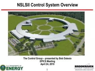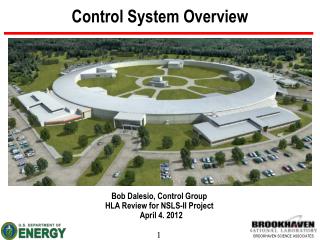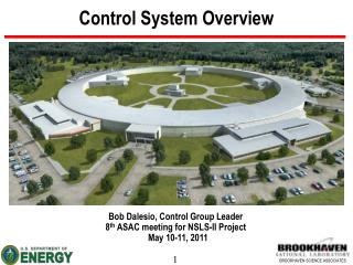
NSLSII Control System Overview
NSLSII Control System Overview. The Control Group – presented by Bob Dalesio NSLS-II ASAC Review October 14, 2010. Outline. Fast Orbit Feedback Component Development High Level Application Status Documentation of Facility in an Relational DataBase - IRMIS EPICS Extensions

NSLSII Control System Overview
E N D
Presentation Transcript
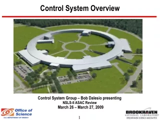
NSLSII Control System Overview The Control Group – presented by Bob Dalesio NSLS-II ASAC Review October 14, 2010
Outline • Fast Orbit Feedback Component Development • High Level Application Status • Documentation of Facility in an Relational DataBase - IRMIS • EPICS Extensions • Control System Studio (CSS) Tools • Subsystem Status and Standards • Conclusions
Orbit feedback system architecture Fast orbit feedback system in one cell
Orbit feedback system architecture NSLS-II two tier device controller architecture Cell 1 Cell 30 Cell 2 Cell 29 Cell 3 Storage Ring SDI link SDI link Cell 17 Cell 15 Cell 16
Fast Orbit Feedback – Time Budget 6.7 µs for BNL BPM Electronics delay to pipeline 3.7 µs for analog value averaged from raw data 3 µs estimated for BNL BPM Electronics 57 µs measured on Libera BPM Electronics with minimum filter 7 µs measured BPM data distribution by Shared Memory 14 µs measured when one of the redundant links not operational 4 µs measured for FOFB calculation with separate mode compensation 5 µs measured for set power supply by PS Shared Memory link 8 KHz measured for fast corrector PS bandwidth w 10 deg phase shift. 1 KHz measured for corrector magnet/chamber bandwidth. Measured on with Inconel beampipe. This value is at 10 degree phase shift. New magnet/chamber set up will be tested when they are available.
Fast Orbit Feedback Test Stands Digital Front End Board and BPM analog electronics Digital Front End with Cell Controller I/O Soft IOCs PPS Test Stand Power Supply Controllers Power supply interface modules
Fast Orbit Feedback • Digital Front End • redundant ring communication working at 2.5 Gbps • embedded event receiver with <5 psecs jitter and 8 nsecs of resolution. • Second spin will upgrade the FPGA from a Virtex 5 to a Virtex 6 – February time frame • Digital Front End (DFE) Used as Beam Position Monitor (BPM) Front End • raw analog at 116.9 MHz to Memory for up to 1 Gbytes • turn by turn data at 378KHz to Memory for up to 32 MB (2.5 seconds) • transfer of large arrays at under 2 minutes for under 32 MB over Modbus over Ethernet • transfer of large arrays at under 16 seconds for 32 MB over Ethernet • 10 Hz BPM data to Memory; • has several hundred DSP slices for digital filtering • Virtex 5 has >90% Memory registers in use – Virtex 6 will give us 5x more. • Digital Front End Used as Cell Controller • calculates fast orbit feedback algorithm for local in 4 microseconds • matrices for up to 90 eigenvectors; • I/O board can be used for fast machine protection • 16 digital input, 12 digital outputs and 4 analog outputs for fast machine protection; • four 100 Mbps copper ports for redundant comm links to the fast and slow power supplies. • Power Supply Controller (PSC) is ready for production • provides redundant 100 Mbps network to all power supplies within one cell. • provides Memory access by Modbus protocol over 100 Mbps Ethernet • dedicated fiber from each Power Supply Control to each Power Supply Interface. • Power Supply Interfaces (PSI) is ready for production • demonstrated < 5 ppm long term stability • takes 10 KHz data for up to 10 seconds for diagnostics • 20 bit DAC (1 ppm resolution), 16 bit ADCs for DCCT
High Level Applications (HLA) • High level applications requirements are identified and being refined • High level application architecture is client/server • based on the EPICS version 4 network protocol, PVAccess • One server provides results to all clients • New data types have been defined for multichannel arrays, multidimensional arrays, images, statistical samples, tables (arbitrary collections). • These are being implemented in PVAccess • Servers are completed that provide: • Model Results • List of process variables based on function and attributes • Synchronous vector of data given a list of process variables. • Other Services are under development. • Developer document for thin clients is being written in conjunction with the physics group. • Standard clients in CSS can be used to display HLA data
Client-Server Architecture for HLA Completed MMLT Client Scripting HLA Client Early Development Being Extended PVAccess/CAC PVAccess/CAC Production HLA Client Control System Studio Ethernet PVAccess/CAC PVAccess / CAC PVAccess/CAC PVAccess/CAC PVAccess/CAC PVAccess PVAccess PVAccess Magnet Conv, Response Matrix, Dispersion, etc…. Multi-Channel Arrays Svr Save/Compare Restore Svr Channel Finder Svr Model Server Lattice Server Middle Layer Servers SQL Elegant/Tracy SQL SQL Serves orbit, magnets, any array of channels RDB IRMIS IRMIS CAS PVA CAS PVA Diag & PS CAS CAS PVA CAS PVA CAS Utilities etc.., PVA PVA Diagnostics RF Power Supplies Vacuum Distributed Front-Ends LS2 Simulation Physical Device Physical Device Physical Device Physical Device Physical Device
IRMIS • Production tools available for • Component type editor • Component editor • Component Browser • Wiring Editor • Control group members have started to enter component types • Subsystem engineering groups have started to enter component data • Subsystem engineering groups have done initial testing of the wiring editor • Rapid prototyping tools are in place to support developing applications • Lattice • Electronic log • Save Compare Restore (SCORE) • Magnet Measurements • Component Inventory and History • Physics group and mechanical group are working with us on these • IRMIS Crawler, which was developed at Argonne, looks at EPICS configuration files and provides data management. • We have no deployed databases or clients so this is not yet in use.
PERL crawler Rapid Prototype • Rapid Prototype Environment: • lattice • cmpnt inventory • cmpnt history • magnet measurements • traveler • elog • pv_meta • service config (alh, ar, score) • logscore • cmpnt channels • PERL: • epics config software • CA clients • history • Data Services Layer: • component types • cmpnt config (installation) • cables, tray partitions DSL
EPICS Extensions • EPICS core extensions • Client specified filtering for rate limiting, dead bands, and sub arrays. • State record primitive to provide modular solution to motion and multistate devices such as valves that need to capture transition times and timeouts. • New modular interface to event generator and event receiver • C++ Implementation of PVAccess servers to serve V3 databases • Control System Studio – User Interface Tools • Adopted CSS for our user interface after evaluation • Redeveloped build environment and had it adopted by the collaboration • Developed a name server to return process variables by function • Developed a channel access package to provide all client functions and time synchronous vectors from an arrays of process variables. • Developed multichannel visualization tools
CSS Tools Adopted - Data Browser Plot ‘live’ and historic data over time (combination of striptool and archive viewer)
CSS Tools Adopted - BOY BOY is an Operator Interface (OPI) development and runtime environment.
CSS Tools Adopted - BOY BOY runtime environment/example OPI screens
Developed Tools - ChannelFinder Viewer Used to search for channels by name, properties tags. Sort, filter tag channels
Developed Tools - Multi channel Viewer • Same set of channels • Fig1. sorted by position • Fig2. sorted by name
Subsystem Status • Subsystem Responsibilities • Timing Joe Delong, Jayesh Shah • Diagnostics Yong Hu, Kiman Ha, and Huijuan Xu (Steve Hunt) • Power Supplies Yuke Tian, Shweta Saraf • Vacuum equipment Huijuan Xu • Equipment Protection System David Dudley • Personnel Protection System David Dudley • RF Joe Delong, Michael Davidsaver • Beam Line Control Daron Chabot, Wayne Lewis • Insertion Device Control Daron Chabot, Wayne Lewis • Facility Control Sheng Peng • Network / File Servers Robert Petkus • Physics Application Guobao Shen, Nikolay Malitsky • Preliminary Design Complete for all machine subsystems. Good progress on beam line control. • Prototypes are under development and continue to verify requirements are met. • Final Design will include: • Extended Preliminary design to include: • Final hardware selection • Software packages identified and specified • Complete Component Type definitions in IRMIS • Complete signal counts completed
Subsystem Test Stands Network Design Complete Core switches ordered ($320K) Vacuum Lab Diagnostics Fast Digitizers and cPCI crate Application File SeVacrver Timing Hardware Soft IOCs IRMIS Redundant Servers w/ Raid Disks Radiation Monitor Test Stand PPS Test Stand EPS Test Stand Image Acquisition Test Stand Motion Control Test Stand
Subsystem Standards (1 of 2) • Application Development Environment – Established in Mercurial • Naming Convention • established early by project management • distributed responsibility • Component types and installed components to be documented through IRMIS • Equipment standards (developed with each group): • Timing – established Micro Research Finland as standard • Diagnostics – standard for each class of problem • Vacuum – standard interfaces for serial devices being determined. • Equipment Protection System –Allen-Bradley and Siemens standard for PLCs established and in use for all project PLCs, We integrate PLC data into EPICS • Personnel Protection System – Siemens and Allen-Bradley Safety PLC selected. We implement B chain. • RF – controllers are under development. Not yet integrated. • Turnkey contracts include statements to use the standards as defined in each subsystem by NSLS II.
Subsystem Standards (2 of 2) VME Crates – two vendors that we are evaluating: Elma and Weiner cPCI Crates – under evaluation Soft IOCs – Linux servers – same as used for control room applications. Processors – Motorola and Intel processors being evaluated PLCs – Allen Bradley chosen as standard – putting together standard component list External vendors have Siemens as an option. Timing – Micro Research Finland latest series chosen Camera – Proscilica with GigE interface chosen Fill Pattern – Acqiris chosen. DCCT has GE digitizer under evaluation. Cell controller – First spin operational – Ready for spin 2 – moving to Virtex 6 BPMs – First spin operational – Ready for spin 2 - Libera still a backup plan. Power supplies – in house development I chosen – ready for production. Racks are specified by electronics group Switches – Brocade and Juniper under evaluation Core Switches – Brocade chosen – purchase order out. Motion control – Delta Tau and Galil under consideration. Delta Tau meets all requirements.
Conclusions • The cell controller, power supply controller, and beam position monitor digital hardware is all running • A second spin for the DFE will be completed in February • The PSC and PSI are ready for production. • The Cell controller can support 100 microsecond machine protection if needed • The High Level Physics Application architecture is in place and being used as each service and application is prototyped. • The IRMIS tools are well supported by the developers and have gained acceptance outside of the control group. • Management support is strong to assure success. • An active collaboration is started with FRIB. • Our preliminary designs are complete and final designs are started for all subsystems except beam line controls. • We are ahead of schedule in prototyping all subsystems in order to provide timely decisions on hardware and software standards. • The control team has established critical mass and has very strong momentum.