Download

1 / 62
640 likes | 1.18k Vues
GMV9, and GCV9. TUBULAR GAS FURNACE. Heating Capacity. Cooling Capacity. Supports a wide range of Cooling requirements. VENT TERMINATION CLEARANCES. STANDARD CONNECTIONS. VERTICAL TERMINATIONS (DUAL PIPE). STANDARD HORIZONTAL TERMINATIONS. ALTERNATE HORIZONTAL VENT TERMINATIONS.

E N D
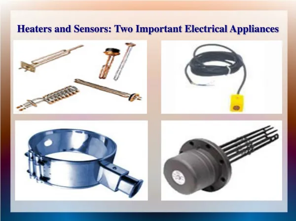
GMV9, and GCV9 TUBULAR GAS FURNACE
Cooling Capacity Supports a wide range of Cooling requirements
Thermostat Options • Single-stage heating/Single-stage cooling • Two-stage heating/Single-stage cooling • Two-stage heating/Two-stage cooling • Fossil fuel application (Kit required) • Three-stage heat pump thermostat required
New Pressure Switch Check • There are 3 Pressure Switches • Hi and Low Fire are grouped together • The Pressure Switch by itself is the Cover Switch • All Pressure Switches are open Switches
Induced-Draft Blower • Jackel 2-speed blower assembly • Motor suspended on four motor mounts for vibration-free operation • Factory-installed rubber discharge makes venting a snap • Alternate flue/vent through RIGHT side with GMV9 and LEFT side for GCV9 Air flow
Integrated Control Board 24V Terminal block D-hum,W2,W1,R,G,B,Y,YLO,O 16-pin connector (ECM Motor) Yellow Dehumidification LED 3 amp Fuse Green CFM LED ICM Microprocessor 12-pin connector (Diagnostics) Red Diagnostic LED 5-pin connector (inducer/ignitor) Hot Connections (Line, XFMR, EAC, HUM) Neutral Connections (Line, XFMR, EAC, HUM)
Single-stage Thermostat? Set dip switch #3 Off = 5 minutes On = 10 minutes Then Move this jumper to the left Easily converted from 2-stage to 1-stage T-stat operation
Accessories Supported • Dehumidistat (Yellow LED indicator) • 115-volt Humidifier (1 amp @ 120 volts) • 115-volt EAC (1 amp @ 120 volts) • 24-volt Humidifier
CFM LIGHT • Green Light On The Bottom Right Side Of The Board • 1 Blink For Every 100 CFM
Start-Up Procedure 1 Connect 115 power, proper grounding and polarity 2 Continuous flash indicates reverse polarity 3 Follow I&O procedure for natural or LP gas 4 Refer to Spec Sheet for correct cfm/temp rise 5 Determine correct system cooling cfm 6 Green cfm LED flashes once per 100 cfm 7 Adjust blower speed using ICM dip switches 8 Turn off power for 10 sec after each adjustment 9 Verify new cfm with green LED 10 Select cooling speed with dips 1,2,3, & 4 11 Select desired ramp profile with dip 5 & 6 12 Select heating speed with dip 7 & 8
Select Cooling Speed Find proper cooling tap in PDB based on ~400 cfm/ton
Select Auto-Comfort Profile Select Profile D for Auto-Comfort Mode
Select Heating Speed Select slowest heating speed possible while maintaining temp rise for minimum energy usage
SEQUENCE OF OPERATIONS COOLING • RY&G Are Energized (Hi-Cooling) Call for Cooling • Condenser Turns On and the Blower Ramps Up to Cooling Speed, EAC Terminal are Now Energized • System Runs Till T-Stat is Satisfied • Outdoor Unit Turns Off and Blower Continues for 45 Seconds, Blower is Ramped Down and EAC Terminals are Turned Off • In Constant Fan Mode, Fan Continues at 56% of Cooling Speed
SEQUENCE OF OPERATIONHeating • R & W1 (Low Fire) Call For Heat • Inducer Draft Motor Starts Pre-Purge on Hi Fire (10 seconds), Humidifer Terminals are energize • Inducer Draft Motor drops to Lo, Low Fire Pressure Switch Closes • Igniter warms up 5 Min. to 9 Seconds opens on Max. • Gas Valve opens on Low Fire ,…… Flame Sensor Detects Flame • If Call for Hi-Heat , Inducer Draft Motor and Gas Valve Jumps up to Hi-Fire • Blower Delay Starts Blower To Ramp Up for 30 Seconds
SEQUENCE OF OPERATIONSHeating 8. EAC Terminal Energized Unit is Now Heating 9. If T-Stat Call for Low Fire, Inducer Draft Motor and Gas Valve Jump to Low Fire till T-Stat is Satisfied 10. Call for Heat Has Been Satisfied, Gas Valve Shuts Off and Inducer Draft Motor Does a Pre-Purge (15 Seconds) 11. Selected Heat-Off Delay 90, 120,150, 180 Seconds and Then the Blower Ramps Down
Field Returns • Handling Boards by Edges or Use ESD Ground Strap • No Repeated Control Change-out • Moisture Control in Board Area • Return Tag Information • Boxes or Bags for Field Returns
Understanding ECM Motors What does ECM mean? Electrically Commutated Motor
AC POWER POWER AC TO DC POWER ECM CONDITIONING CONVERTER INVERTER MOTOR HVAC SYSTEM CONTROL INPUTS 24VAC MOTOR Compressor CONTROL On/Hi/Lo FanOn RevValve Aux/Emerg Heat CapacitySelect Available Outputs CFM How Does the ECM Work?
How Does the ECM Sense Static Pressure? Input Power vs. RPM 550 500 450 P = kN^3 400 1000 RPM 1/2 N = 1/8 P 350 280 Watts 300 1/8 X 280W = 35W Input Power (watts) 250 200 500 RPM 150 35 Watts 100 50 0 250 300 350 400 450 500 550 600 650 700 750 800 850 900 950 1000 1050 1100 1150 RPM
ECM Advantages • Efficiency gain Lower static pressure yields greater efficiency gain
0.8 0.7 0.6 0.5 745W • ® 0.4 0.3 0.2 408W • ® 0.1 0 1300 1400 1500 1600 1700 1800 1900 2000 2100 2200 2300 2400 ECM Advantages • Static-independent Airflow Set the airflow and go! • System airflow is starved • insufficient cooling/heating • liquid refrigerant return • to condenser • Over blowing the system • poor moisture removal • high power consumption • moisture in the duct work PRESSURE Typical profile with a PSC motor Airflow (CFM)
How Does the ECM Work? Motor Connector • The End Bell defines motor characteristics. • Only 3 motor sections ½, ¾, or 1 hp. • The motor is really a three phase motor with a permanent magnet rotor. Motor Section End Bell Assembly
Service and Installation Basics
Power Connectors • Connectors are keyed • Don’t force in the wrong orientation • Pull on the plug, NOT the cable • DO NOT pull power cable out during • operation – Arching could occur Low Voltage 16 PIN CONNECTOR High Voltage 5 PIN CONNECTOR
Power Connectors Continued 5 Pin Power Connector • 120 VAC uses a jumper (red wire) • Control operates at 240 VAC • Jumper enables voltage doubler • Do not apply 240 VAC with jumper installed as motor and • control will fail. • 240 VAC input does not use a JUMPER 16 Pin Signal Connector • Pulse Width Modulation (PWM) or • 24 VAC Thermostat Mode or • Digital Serial Interface (DSI) Operating Voltages Application Note
Troubleshooting ECM Motors What is Normal? • It is normal for the blower to rock back and forth at start up. • It is normal for the shaft to feel rough or bumpy when turned. • Don’t judge the motor by the RPM or ramp up sequence.
Troubleshooting ECM Motors • Don’t judge the motor by the RPM or ramp up sequence. off All slew rates are controlled Profile A Profile B Profile C on Off Delay Short run Full capacity Pre-run Time: 0 - 15 min, 16 steps Level: 6 - 100% 16 steps
Troubleshooting ECM Motors • The # 1 failure of ECM motors…………… No Fault Found ! (80%) • The # 2 failure of ECM Motors …………… Moisture. (16%) • All other failures (4%).
Troubleshooting ECM Motors • Always make sure the motor is oriented such that the connectors are on the bottom • Make sure the electrical connections form a drip loop to prevent any moisture from running down the harness and into the end bell assembly. • A blower wheel loose on the motor shaft can cause the blower to vibrate, excessive noise, and may cause motor malfunction. Drip Loop Electrical Connections on Bottom
Troubleshooting ECM Motors There are some ECM motor testers on the market today.
GE TECMateXLTM Service Tool • Analyzes the GE ECMindependent of the HVAC system • Can test the basic settings: Fan-only, Heating, Cooling and Dehumidification • Will detect and isolate motor failures from HVAC system failures • Accurate and quick diagnosis means better customer satisfaction • Don’t even have to take the motor out of the blower Buy it on www.thedealertoolbox.com. Click on the TECMateXLTM Service Tool link under the Service Tools tab.