Download
1 / 30
300 likes | 481 Vues
Gas Furnace Planned Maintenance. Annual Fuel Utilization Efficiency (AFUE). Percentage of the annual average efficiency of a furnace All furnaces manufactured after 1992 must have a AFUE of at least 78%. Types of Gas-Fired Furnaces. Natural Draft Induced-Draft Condensing.

E N D
Annual Fuel Utilization Efficiency (AFUE) • Percentage of the annual average efficiency of a furnace • All furnaces manufactured after 1992 must have a AFUE of at least 78%
Types of Gas-Fired Furnaces Natural Draft Induced-Draft Condensing
Natural Draft Furnaces • Rely on the buoyancy of the hot combustion products to create the draft needed to draw combustion products through the heat exchanger and out the vent • Difficult to obtain a 78% AFUE rating • Not being produced by most manufacturers
Induced-Draft Furnaces • Have an AFUE of at least 78% • Use an inducer fan to draw the products of combustion through the heat exchanger • Inducer fan restricts the flow of warm air out the vent during the off cycle
Condensing Furnaces • Have an AFUE rating of at least 90% • Have an additional heat exchanger which removes the latent heat from the flue gas by condensing the water vapor • Side wall venting • Draws in 100% combustion air from outside
Furnace Configurations Upflow Downflow Horizontal Multipoise
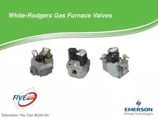
Gas Furnace Components Gas Valve Gas Manifold and Orifices Gas Burners Heat Exchangers Burner Ignition Devices
Gas Valves • Most furnaces will use a combination gas valve • The basic function of a combination gas valve is: • Automatic and manual shut-off of gas flow to the main burners & pilot • Pressure adjustment and regulation of the gas supplied to the gas manifold & pilot
Gas Valves continued…. • Natural gas furnaces use a combination gas valve--it should be adjusted to regulate the outlet gas pressure to 3.2” w.c. to 3.8” w.c. • LP furnaces may not have a pressure regulator adjustment; if it does, it should be adjusted to regulate the outlet pressure to 10.5” w.c. to 11” w.c.
Gas Manifold & Orifices • Spuds can be changed in the field to obtain the correct burner input rate • The spud controls the flow of gas to each of the burners • The exact orifice size of the spud is determined by the manufacturer
Gas Burners • Properly mix the gas with the combustion air to the combustion chamber • Two types: • Multi-port • Mono-port • The amount of primary air supplied to some multi-port burners can be changed by adjusting the primary air shutter
Burner Ignition Devices Three basic types Standing Pilot Pilot Re-ignition Direct Ignition
Standing Pilot • Two types of safety devices: • Thermocouple • Thermally-actuated switch • Clean orifice carefully • A properly adjusted pilot flame will have a soft blue color with some yellow at the tip • Should have a height of 3/8” to 1/2” to impinge on the thermocouple
Standing Pilots continued... • Normal output voltage of thermocouple is 26 to 32 millivolts DC • The minimum acceptable output voltage is 12 millivolts DC • If pilot flame goes out the gas flow to the pilot assembly should drop out within 2-1/2 minutes.
Spark Re-ignition • Used on mid-efficiency & high-efficiency furnaces • Output spark typically 15,000 volts • Pilot flame is proved by either a set of thermally-actuated switches or a flame rectification circuit (more common) • Never attempt to manually light
Spark Re-ignition continued... • Clean the components of any dirt, scale, soot or carbon using a soft-bristle brush • Check high voltage cable for any cracks or poor connections • Check safety lockout operation • With gas valve off set thermostat to call for heat, see if gas valve shuts down if no flame is proved
Direct Ignition(Hot Surface Ignitor) • Used on high efficiency furnaces • Hot Surface Ignitor directly lights burners • Uses flame rectification circuit to prove flame • Made of ceramic - fragile • Visually inspect for cracks or breaks • At room temperature the resistance should equal 45 to 90 ohms (if over 110 ohms replace)
Vent Checks • Visually check for any obstructions • Visually check for any worn or damaged pipes • If any problems observed, immediately notice the proper personnel • Inspect vent pipe to other appliances that may be tied into the furnace(s)
Temperature Rise Checks • Determine temperature rise for data plate • Generally low-efficiency furnaces will have a temperature rise of 75 to 100 degrees • Generally high-efficiency furnaces will have a temperature rise of 40 to 70 degrees • Always check supply temperature out of the line of sight of the heat exchanger
Temperature Rise Checks continued... • Before checking the temperature rise of a furnace make sure the filter is clean and the airflow is not being blocked • Use the same type of thermometers for measuring the return and supply temperatures • Before checking the temperature rise, compare the accuracy of each thermometer against each other
Safety Controls Checks • Verify the operation of the high temperature switch. • Block return airflow completely and observe the gas valve shutting down and at which temperature • On induced draft furnaces remove one end of the rubber hose from the air pressure switch and observe the gas valve shutting down