Comprehensive Guide to Modulation Accuracy Testing in Wireless Communications
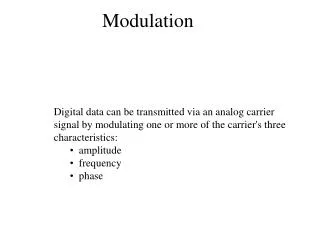
Learn about modulation accuracy tests, including transmit center frequency leakage, transmitter constellation error, and transmitter modulation accuracy tests. Understand the methodologies and specifications for achieving accurate modulation in wireless systems.

Comprehensive Guide to Modulation Accuracy Testing in Wireless Communications
E N D
Presentation Transcript
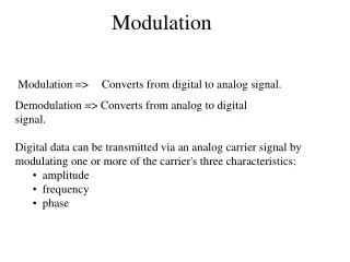
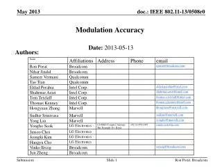
Modulation Accuracy Authors: Date:2013-05-13 Ron Porat, Broadcom
Authors continued: Ron Porat, Broadcom
Authors continued: Ron Porat, Broadcom
24.3.17.4 Modulation accuracy • This section is currently empty. We propose text for all subsections • 24.3.17.4.1 Introduction to modulation accuracy tests • 24.3.17.4.2 Transmit center frequency leakage • 24.3.17.4.3 Transmitter constellation error • 24.3.17.4.4 Transmitter modulation accuracy (EVM) test • The proposed text is based on 11ac with slight modifications as appropriate for 11ah Ron Porat, Broadcom
24.3.17.4.1 Introduction to modulation accuracy tests • Transmit modulation accuracy specifications are described in 24.3.17.4.2 (Transmit center frequency leakage) and 24.3.17.4.3 (Transmitter constellation error). The test method is described in 24.3.17.4.4 (Transmitter modulation accuracy (EVM) test). Ron Porat, Broadcom
24.3.17.4.2 Transmit center frequency leakage • TX LO leakage shall meet the following requirements for all formats and bandwidths : • When the RF LO is in the center of the transmitted PPDU BW, the power measured at the center of transmission BW using resolution BW 31.25 kHz shall not exceed the average power per-subcarrier of the transmitted PPDU, or equivalently, ( ), where P is the transmit power per antenna in dBm, and NST is defined in Table 24-4 (Timing-related constants). • When the RF LO is not at the center of the transmitted PPDU BW, the power measured at the location of the RF LO using resolution BW 31.25 kHz shall not exceed the maximum of -27dB relative to the total transmit power and -15dBm, or equivalently , where P is the transmit power per antenna in dBm. • The transmit center frequency leakage is specified per antenna. Ron Porat, Broadcom
24.3.17.4.3 Transmitter constellation error • The relative constellation RMS error, calculated by first averaging over subcarriers, OFDM PPDUs and spatial streams (see Equation (20-89)) shall not exceed a data-rate dependent value according to Table 24-32 (Allowed relative constellation error versus constellation size and coding rate). The number of spatial streams under test shall be equal to the number of utilized transmitting STA antenna (output) ports and also equal to the number of utilized testing instrumentation input ports. In the test, NSS=NSTS (no STBC) shall be used. Each output port of the transmitting STA shall be connected through a cable to one input port of the testing instrumentation. The requirements apply to 1 MHz, 2 MHz, 4 MHz, 8 MHz and 16 MHz transmissions. • Table 24-32 Ron Porat, Broadcom
24.3.17.4.4 Transmitter modulation accuracy (EVM) test The transmit modulation accuracy test shall be performed by instrumentation capable of converting the transmitted signals into a stream of complex samples at sampling rate greater than or equal to the bandwidth of the signal being transmitted; except that for duplicate transmissions, each 1 MHz or 2 MHz subchannel may be tested independently while all subchannels are being transmitted. The instrument shall have sufficient accuracy in terms of I/Q arm amplitude and phase balance, DC offsets, phase noise, and analog to digital quantization noise. A possible embodiment of such a setup is converting the signals to a low IF frequency with a microwave synthesizer, sampling the signal with a digital oscilloscope and decomposing it digitally into quadrature components. The sampled signal shall be processed in a manner similar to an actual receiver, according to the following steps, or equivalent procedure: • Start of PPDU shall be detected. • Transition from STF to LTF1 shall be detected and fine timing shall be established. • Coarse and fine frequency offsets shall be estimated. • Symbols in a PPDU shall be de-rotated according to estimated frequency offset. • For each LTF symbol, transform the symbol into subcarrier received values, estimate the phase from the pilot subcarriers, and de-rotate the subcarrier values according to the estimated phase. • Estimate the complex channel response coefficient for each of the subcarriers and each of the transmit streams. • For each of the data OFDM symbols: transform the symbol into subcarrier received values, estimate the phase from the pilot subcarriers, de-rotate the subcarrier values according to the estimated phase, group the results from all the receiver chains in each subcarrier to a vector, and multiply the vector by a zero-forcing equalization matrix generated from the estimated channel. • For each data-carrying subcarrier in each spatial stream, find the closest constellation point and compute the Euclidean distance from it. • Compute the average across PPDUs of the RMS of all errors per PPDU as given by Equation (20-89). The test shall be performed over at least 20 PPDUs ( as defined in Equation (20-89)). The PPDUs under test shall be at least 16 data OFDM symbols long. Random data shall be used for the symbols. Ron Porat, Broadcom
Straw Poll • Do you support the proposed text in slides 5-8? • Yes • No • ABS Ron Porat, Broadcom