Download
1 / 48
480 likes | 807 Vues
NCSX Stellarator Core Pre-conceptual Design Progress and Status. Mike Cole, Paul Goranson, Brad Nelson, Dave Williamson NCSX PAC Meeting PPPL June 3-4, 1999. Presentation Outline. Requirements overview What must the stellarator core do?

E N D
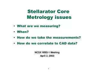
NCSXStellarator CorePre-conceptual Design Progress and Status Mike Cole, Paul Goranson, Brad Nelson, Dave Williamson NCSX PAC Meeting PPPL June 3-4, 1999
Presentation Outline • Requirements overview What must the stellarator core do? • Stellarator core configuration What is the design concept? • Evaluation Will it work? • Issues What are we worried about? • R&D How do we plan to resolve the issues?
Baseline parameters for core design studies____________________________________________ • Pre-assembled, “drop in “ stellarator core, consisting of vacuum vessel, saddle coils, and saddle coil structure • Option 2C - Re-use PBX TF, PF coils and structure • C10 plasma with SAD18.5_16 coil set, LN cooled • 26 coils per period • 84 kA/coil at 2 Tesla field on axis • 400 m total winding length • 16 x 70 mm winding size, ~ 17,500 A/ cm ^2 • Vacuum vessel is stand-alone, structural vessel bake-able to 350C
NCSX in the PBX Facility____________________________________________
Proposed Stellarator Core Concept • Plasma-Shaped Vacuum Vessel • Inner Structural Shell (“apple core”) • Outer Structural Shell • Saddle Coils Wound on Outside of Shell • Fiberglass cryostat
Saddle Coil Design Basis / Requirements C10A Plasma SAD185-16 Coilset Dist from Plasma to Coil 18-cm Longest Coil Length (1-turn) 16.7-m Total Length of Conductor 4080-m Total Weight of 78 Coils 6000-lb
Proposed Concept General Arrangement Inner Coil Structure Vacuum Vessel Outer Coil Structure
Proposed Concept Design Features Element Material (Shell) Poloidal Segmentation Toroidal Segmentation Assembly Coil Construction & Leads Slot Closure Cooling/ Insulation • Options • Stainless Steel • Aluminum • Bronze • Mid-plane • Top/Bottom • 24 (Wedges) • 120 (Plates/Wedges) • Bolting • Flexible Sq Conductor • Welded Cover Plate • Cooling Line Plug • Compacted Fill/Epoxy • LN Cooling • PBX Vessel / Cryostat Preference Nickel Aluminum Bronze (NAB) Top/Bottom 24 Wedge Segments Bolting Flexible Sq Conductor Cooling Line Plug LN Cooling Line + Fiberglass Enclosure
Proposed Concept - Inboard shell 24 Wedge Segments Inboard Structure Wedge Attachment (1-in dia bolts, 3-in spacing)
Proposed Concept- Outboard shell 24 Wedge Segments Outboard Structure
Fewer segments lowers cost - Segmentation reduced from earlier designs to 8 segments per period - Fewer segments dramatically decreases: - Number of casting patterns (cost) - Machining set-ups and and time (cost) - Number and accuracy of assembly fixtures (cost)
Proposed Concept Coil Leads - Two pancake windings in a full-radius groove - Pancake-to-pancake transition occurs in a pocket in the bottom of the groove - Layer-to-layer transitions are adjacent - Leads transition to coaxial configuration Coaxial Leads Pocket Full Radius
Proposed Concept Coil Leads Coils above mid-plane Mid-plane accessible Coils below mid-plane
Proposed Concept Coil Leads
Performance Evaluation Helical Coils Structure - 16 x 70-mm winding pack, ~17.5-kA/cm2 at 2T - Approx 1-s ESW pulse length, 80-130K temperature rise - Cool-down in <10-min - 8 segments/period give ~20-ms longest time constant - Maximum coil EM load at 2T is ~1900-lb/in - EM loads calculated using ANSYS are in good agreement (~10%) - Maximum bolt load due to EM is 52-kN (shear), 34-kN (axial) - Combined EM/thermal bolt loading TBD, may need additional space
Performance Evaluation Coil Cool-Down After Pulse
What is max field on saddle coil conductor? • Maximum Field at Coil Surface is 5.6-T • Bmax/B0 = 2.8 (2 Tesla toroidal field at 1.45m) • C10, SAD185-16 coil set BMOD Nodal Fringe Plot
What are the forces on the saddle coils? Force Due To Toroidal Field View Inside Looking Out
Do we believe the forces? • EM Forces calculated using two independent methods • ANSYS and MAGFOR agree within 10% Force Vectors (ANSYS) Force Vectors (MAGFOR)
What do the saddle coil forces do to the shell? (m) • C10-2T Load Case (Max Load = 1963-lb/in) • Net Force / Period = -767-kN (radial) • Maximum Displacement = 0.6-mm
Global Shell Stresses are reasonable • Max General Stress = 65-Mpa for 4 cm shell • Peak Stress at Support Points • Grooves not included 65-MPa
Normal Force (kN/m) Lateral Force (kN/m) The smooth shell works, but what about all the grooves? Plasma Config C10-2T, Coil Set SAD185-16, Cut Thru One Half-Period
160 MPa 4 5 6 7 8 9 mm Ligaments between windings must react lateral forces • Conductor Modulus = 1-Gpa • Plasma Config C10-2T, Coil Set SAD185-16, Cut Thru One Half-Period C10
Issue: Current Density and Pulse Length • Current density determines pulse length for adiabatic heating • Current density is a function of number of turns, packing fraction in braided conductor, insulation thickness, allowance for tolerance, ligament width, etc. • Baseline design (C10) • Number of turns per saddle coil = 10 • Current density in copper ~17.5 kA/cm^2 at 2 T • Pulse length for 80 to 130 K rise = ~1 second (equiv square wave) • Power at end of pulse ~45 MW
Relative winding stiffness Thermal stress limits the temperature rise in conductor Winding stiffness determines thermal stress, will be addressed by R&D
Issue: Bad Geometry of Adjacent Windings - Curvature effects can be minimized by making coils parallel in critical regions - Parallel cross sections may provide more space for windings in critical regions - Program using Pro/E geometry has been demonstrated Saddle Coil #1 (Guiding Coil) ~11-deg Coil #2 (Adjusted) Coil #2 (Original)
Proposed Stellarator Core Concept • Plasma-Shaped Vacuum Vessel • Inner Structural Shell (“apple core”) • Outer Structural Shell • Saddle Coils Wound on Outside of Shell • Fiberglass cryostat
Vacuum Vessel Configuration • Liner is a stand-alone, structural vessel that can be baked to 350-C Parameters • Inner radius = 38-in (0.97-m) • Outer radius = 78-in (1.98-m) • Height = 68-in (1.73-m) • Wall Thickness = 0.375-in • Contour Tolerance = +/-5-mm • Inside Surface Area = 58k-in2 • Enclosed Volume = 218-ft3 • Weight w/o PFCs = 8300-lb
Vacuum Vessel Design Choices Material Options - • 316L or 304L stainless steel • lowest material cost option • Inconel 600 or 625 • Low permeability, higher electrical resistivity Status - Inconel 600 chosen for baseline design Fabrication technique Options - • Break bending and welding • Explosive forming, casting, other Status - Break bending chosen for baseline design
Vacuum Vessel Design Choices W 7 - AS/X Fabrication
Vacuum Vessel Design Choices Assembly / Design Integration Options - • One Piece • Best procurement option • Three Pieces • Coil structure design flexibility Status - Three pieces chosen as baseline Heating / Cooling Options - • Water/Steam • DowTherm Status - Dowtherm system like NSTX chosen for baseline
Vacuum Vessel Parameters/Performance 12 MW operation • AVERAGE PLASMA HEAT FLUX 32 w/cm2 • BAKE OUT TEMPERATURE 350 C • OPERATING TEMPERATURE > 38 C • TEMPERATURE RISE DURING PULSE 21 C • 3 sec flat top pulse • 1.27 cm liner • THERMAL LOSS THRU SHELL DURING BAKE OUT 10.4 kW • 2.54 cm thermal blanket • THERMAL LOSS THRU SHELL DURING OPERATION 9.9 kW • 2.54 cm thermal blanket • THERMAL GROWTH DURING BAKE OUT 1 cm radial
Vacuum Vessel Issues will be addressed with R&D • Weld distortion • Bad experience with ATF (but good with W7-AS) • Close control of welding procedures essential • Resolve during R&D phase • Forming • Experience lacking, issues not identified • Resolve during R&D phase
Proposed Stellarator Core Concept • Plasma-Shaped Vacuum Vessel • Inner Structural Shell (“apple core”) • Outer Structural Shell • Saddle Coils Wound on Outside of Shell • Fiberglass cryostat
Proposed Cooling/Insulation/Cryostat Concept - Cryogenic boundary provided by fiberglass enclosure - Enclosure may conform to shell or be more generic in shape - Nitrogen gas flow within prevents frost, cools shell during bake-out - Flexible connection to vessel ports (100-350C) required Vent or Recirculate LN2 Vapor
Coil Design Evolution: C82 vs C10 C-10 C82-FD121
R&D for Stellarator Core • Early R&D has greatest pay-off for design improvements and cost savings • Plan is based on three phases of work for each subsystem • Simple, in-house tests for specific issues (e.g. conductor stiffness test) • Integrated prototype fabrication and tests by vendor (full scale winding) • Follow-on production of final components by same vendor, if possible
Saddle coil winding R&D Conductor Compression Test Compression Test Fixture Goal Establish stress-strain behavior of cable in rigid slot Status Drawings complete and in shop Conductor Sample
Saddle coil winding R&D Winding/Thermal Cycle Test Potting dam Two conductor loops Nickel-Al-Bronze Block 40 Goal Investigate coil behavior during pulse thermal cycles, cool-down Status Drawings out for estimates 6
Summary and Conclusion • We have selected a baseline design configuration and fabrication concept • LN cooled copper braid wound into grooves on segmented shell • Stand-alone, bakeable vacuum vessel made by break-bending • Baseline design developed around C10 coils is workable • >1 second flat-top at 1 Tesla • 2 Tesla operation is structurally ok • Coil set is still evolving • We have a handle on cost drivers, fabrication limits • Coil groups working to reduce number of coils and current density • Several issues remain that will be addressed by R&D