Feedback Circuits
Feedback Circuits. Two inverters, with feedback. If the first input is 0 , a 0 gets fed back into it. 0. 0. 1. If the first input is 1, a 1 gets fed back into it. 1. 0. 1. This circuit will hold its state forever - stable. write. in. out. Changing the value.

Feedback Circuits
E N D
Presentation Transcript
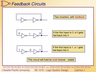
Feedback Circuits Two inverters, with feedback If the first input is 0, a 0 gets fed back into it 0 0 1 If the first input is 1, a 1 gets fed back into it 1 0 1 This circuit will hold its state forever - stable
write in out Changing the value Replace one inverter with a tri-state inverter How can we force this to be either ‘1’ or ‘0’? Add some control logic Add a tri-state inverter for input When write=‘1’, straight connection from input to output – We can write values in This is a simple one-bit memory cell. When write=‘0’, feedback connection – holds state
A B C D E F Ring Oscillators 1 0 0 1 0 1 1 0 0 1 0 1 B C D E F A Odd # of stages leads to ring oscillator Timing Waveform: A and F arethe same wire
R Q R S Q Qb 0 1 1 0 0 0 1 1 Qb S 1 0 1 0 ? 0 0 1 0 1 ? 0 1 1 0 0 Cross coupled NORs NOR: ‘0’ if either of its inputs are ‘1’ S = set R = reset Q = output 1 0 0 1 hold hold When a NOR has one input at ‘0’, it inverts the other input 0 0 WhenR and S are 0 This is called an R-S Latch
R Q Qb S R S Q Qb Nors with R=S=1 Re-examine the inputs R=1 and S=1: What does it mean to both set and reset at the same time?R-S latch says “both lose!” Q and Qb both are 0 • What happens when R=S=1 (Q=Qb=0) and R or S changes to 0? • S changes to zero first Reset wins (Q=0, Qb=1) • R changes to zero first Set wins (Q=1, Qb=0) • Both change at the same time to R=S=0… When R=S=1 changes to R=S=0, we get an uncontrolled oscillation (unstable) 1 0 0 0 1 1 0 1 1 0 1 0 Moral of the story: R=S=1 is bad Make it an illegal input
S’R’+SR’ == R’ S’R+S’R’ == S’ SR’ R S Q Q 0 1 1 0 1 0 0 1 0 0 hold hold 1 1 0 0 Q=1 Q=0 Q=0 Q=1 S’R SR SR SR Q=0 Q=0 SR’ S’R S’R’ S’R SR’ SR+S’R’ Q=1 Q=1 R-S Latch states State: The current status of all memory elements. Changes to states occur only when inputs change All possible inputs must be “covered” by an arc out of each state
Stop GND R Run +5 Start GND S +5 Using an R-S latch R-S Latches are useful whenever a system should “remember” the last input • Design a system with two pushbuttons: Startand Stop • Whenever Start is pushed, the signal Run will be asserted. • Run should remain asserted until Stop is pushed.
Input GND Out +5 OutIdeal OutActual R Input Out GND +5 S GND Switch Debouncing Switch Depressed Switch Released
R Q Q R S Q Q S R Q R En S Q S Q R S Q En An enabled (gated) R-S latch Unclocked R-S Latch Output changes only wheninput changes, and enabled Level-sensitive R-S Latch Clock Signal
R R Q(enabled) Q(regular) S S En Set Set Set S R Reset Reset En Q(regular) Q(enabled) Q Q R R S S Q Q En Regular vs. Enabled R-S latches Assume that latches have no time delay (ideal) Enabled latch only changes when enable is asserted
R Q S Clock Clock(En) Set Set Set S Reset R Reset Q Q R S Q En Clocking an enabled R-S Latch A clocked R-S latch follows the R/S inputs when the clock is asserted. A clocked R-S latch stores the value when the clock goes low whenthe clock is not asserted.
D Q C clk D Q R S Q En clk Clock D Q D-Latches (gated) In a D-latch, the output follows the input when the clock is high. When the clock is low, the output remains what it was on the falling edge of the clock.
D Q en VHDL for D Latches (gated) LIBRARY ieee;USE ieee.std_logic_1164.all;ENTITY Dlatch ISPORT( D : INSTD_LOGIC; en : INSTD_LOGIC; Q : INOUT STD_LOGIC); END Dlatch; Inputs: D and EnOutput: Q INOUT instead of OUT: Can be used as an input within the ENTITY ARCHITECTURE behavior OF Dlatch ISBEGIN PROCESS(D,en) BEGINIF (en = ‘1’) THEN Q <= D;ELSE Q <= Q;END IF;END PROCESS; END behavior; PROCESSlist State of latch can change due to a change in any of these values Continuously monitors D and en looking for changes If enabled, Q D If not enabled, Q keeps its old value