Lecture 10 MPC 555 Interrupt
Lecture 10 MPC 555 Interrupt. Interrupt System Design: Hardware issues. Connect interrupt sources to processor core. Determine ISR addresses using exception vector table. Help software determine interrupt source. Disable/enable interrupts. Mask interrupts. Interrupt setup

Lecture 10 MPC 555 Interrupt
E N D
Presentation Transcript
Interrupt System Design: Hardware issues • Connect interrupt sources to processor core. • Determine ISR addresses using exception vector table. • Help software determine interrupt source. • Disable/enable interrupts. • Mask interrupts.
Interrupt setup Set up interrupt level Set up exception vector table Set up interrupt mask Enable interrupt Device-specific setup Interrupt Processing Create/destroy stack frame Save/restore machine states and EPC Mask interrupt (optional) Enable interrupt (optional) Save/restore registers contents Determine interrupt source Determine ISR address Device-specific processing Interrupt System Design: Software Issues
MPC555 Interrupt Overview MPC555 Interrupt Sources: • External I/O devices • Internal I/O device • From USIU inside (Unified System Interface unit) USIU includes interrupt control Internal I/O 2 1 External I/O Processor Core 3 USIU handler memory
PowerPC Internal I/O Modules • TPU3: Time Processor Units, 3rd version; versatile functions, e.g. counting pulses • MIOS1: Modular I/O System; • QADC64: Queued Analog-to-digital converter • TouCAN: Control Area Network, two-wire, up to 1Mbps and 40m; e.g. network inside vehicle • QSMCM: Queued Serial Multi-channel Module • IMB3 bus: Inter-Module Bus TPU3 TPU3 MIOS1 QADC64 QADC64 TouCAN TouCAN QSMCM 1 IMB3 Bus
UIMB: U-bus to IMB Interface IMB3 Bus • UIMB: U-bus to IMB interface • UIPEND: Interrupt pending reg. • U-bus: Unified bus, connecting multiple internal buses • UMCR[IRQUX]: Enable level 7-31 32 2 addr/data UIPEND UMCR[IRQUX] 8 U-Bus Other bus Interruptcontroller
UIMB: U-bus to IMB Interface The interface converts 32 interrupt levels on IMB3 Bus to 8 interrupt levels on U-Bus • Level 0-6 to U-Bus level 0-6 • Level 7-31 to U-Bus level 7 • Interrupt handler reads full UIPEND through memory-mapped I/O
External Interrupts U-BUS 2 Other I/O device: • Hard drive, video card, … • IRQ[0]: connect to reset IRQ[0:7] 8 external 8 3 1 4 USIU IRQ 1 Reset 1 Timer
Unified System Interface Unit The USIU controls system start-up, system initialization and operation, system protection, and the external system bus. MPC555 USIU functions: • System configuration and protection • Interrupt controller • System reset monitoring and generation • Clock synthesizer • Power management • External bus interface (EBI) control • Memory controller • Debug support Internal I/O Processor Core USIU
Interrupt Controller Internal I/Othrough U-bus External IRQ USIU 4 Timebase SIPEND Clock SIMASK PIT SIVEC PLL IREQ SW watchdog NMI control reset Decr timer Decrementer Note: External IRQ is controlled by SIEL – triggered by falling edge or low level
Interrupt Controller SIPEND[0:31]: Interrupt pending register • Handler accesses SIPEND for source of interrupt • Bits 0-15 record interrupt source; 16-31 reserved • External IRQ[0:7]: accessing SIPEND is enough • Internal IMB3 device: further accessing UIPEND SIMASK: mask register • If SIMASK[i]= 0, then SIPEND[i] is blocked • SIMASK[0] = 0 has no effect SIVEC: interrupt vector register • Index to exception vector table • Accessed by interrupt service routine (ISR) NMI control: non-maskable interrupt control • External IRQ[0] is non-maskable • SW watchdog is non-maskable
USIU Internal Interrupt Sources MPC 555 has a crystal of 4MHz or 20MHz • Time base: timer interrupt based on the clock; cannot be reset • Real-time clock: timer interrupt based on real-time clock (like a watch); cannot be reset • PIT: Periodic interrupt timer – goes off every n cycles • PLL change of lock: Phase lock loop, used to provide higher clock frequency; generate interrupt in abnormal situation, e.g. lost the lock of the clock • Software watch dog: Used to monitor help avoid software deadlock • Decrementer: Another timer interrupt, but is processed by a special handler (less overhead)
Three interrupt lines to processor core: IREQ, NMI, and Decrementer MSR[EE]: Enable external interrupt IREQ: External interrupt NMI: Non-maskable interrupt (e.g. reset button is pushed) Decrementer: fast timer interrupt Other processor components not shown Connecting To PowerPC Core 5 Finally! IREQ MSR[EE] Vector table 1 inst addrto mem & n+0x100 n+0x500 NMI 2 n+0x900 Decrementer 3 SSR0 SSR1 inst Inst buffer
Connecting To PowerPC Core Refers to three handlers for • Maskable Interrupt • Non-maskable interrupt • Decrementer (low-overhead timer) When an interrupt happens, hardware: • Waits for current inst to complete • Saves MSR[EE] to SSR0, Clears MSR[EE] • Saves PC to SSR1 • Transfer control to n+0x100,n+0x500, or n+0x900, respectively The rest is left to software handler All I/O interrupts share the same interrupt handler
MPC555 Interrupt All Together 1 2 3 4 5
SIPEND SIMASK 31 31 16 16 I0 I0 L0 L0 I1 I1 L1 L1 I2 I2 L2 L2 I3 I3 L3 L3 I4 I4 L4 L4 I5 I5 L5 L5 I6 I6 L6 L6 I7 I7 L7 L7 reserved reserved MPC555 Interrupt Summary From IMB3 peripherals L7 for 7-31 L0 L1 L2 L3 L4 L5 L6 UIPEND External IRQ[0:7] I1 I2 I3 I4 I5 I6 I7 I0 Priority arbiter IRQ 8-bit vector: SIVEC
Interrupt setup Set up interrupt level Set up exception vector table Set up interrupt mask Enable interrupt Device-specific setup Interrupt Processing Create/destroy stack frame Save/restore machine states and EPC Mask interrupt (optional) Enable interrupt (optional) Save/restore registers contents Determine interrupt source Determine ISR address Device-specific processing Recall Software Issues
Interrupt Priority And Codes SIVEC contains a 8-bit interrupt code or vector for each source • Priority Int. source Int. Code • 0 (highest) IRQ[0] 0x0 • 1 Level 0 0x4 • 2 IRQ[1] 0x8 • 3 Level 1 0xC • 4 IRQ[2] 0x10 • … … … • 15 Level 7 0x3c Help determine interrupt source
USIU Internal interrupts Come from: PIT, Time Base (TB), Real-time Clock (RTC), Phase lock loop change of lock (PLL). They can be programmed to come at Level 0-7: Level 0: 1000 0000 : 0x80 Level 1: 0100 0000 : 0x40 Level 2: 0010 0000 : 0x20 Level 3: 0001 0000 : 0x10 Level 4: 0000 1000 : 0x08 Level 5: 0000 0100 : 0x04 Level 6: 0000 0010 : 0x02 Level 7: 0000 0001 : 0x01
0x0 IRQ0 ISR addr IRQ0 ISR addr 0x4 Level0 ISR addr 0x8 IRQ1 ISR addr 0xc Level1 ISR addr 0x10 IRQ2 ISR addr 0x14 Level2 ISR addr 0x38 IRQ7 ISR addr 0x3c Level7 ISR addr Use SIVEC and IRQ Table Determine ISR address IRQ_Table_Base ISR-Address = Mem[IRQ_Table_base + Interrupt code] Interrupt code is in register SIVEC, memory mapped to address SIVEC (0x2F C01C) lis r3, SIVEC@h lbz r3, SIVEC@l(r3) lis r4, IRQ_Table_Base@H ori r4, r4, IRQ_Table@L add r4, r3, r4 lwz r4, 0(r4) mtlr r4 blrl #branch to ISR
RI=1: recoverable Machine State Register (MSR) 0 EE PR 0 IP IR DR 0 0 RI LE IP=0: exception Vector table Starts at 0x000 else 0xfff PR=0: supervisor =1: user EE=ext. interrupt enable =0: disable =1:enable LE=0 Big-endian Machine State Register
On an exception: IL E E E P R I P R I L E 0 0 0 MSR PPC Exception Registers mtspr SRR0, r2: r2 SRR0 mfspr r3, SRR1: SRR1 r3 mtmsr r2: r2 MSR mfmsr r3: MSR r3 Each exception handler must save SRR0, SRR1, and MSR before enabling exceptions (EE=1).
Machine Status Save/Restore Register 0 (SRR0) PC saved here Machine Status Save/Restore Register 1 (SRR1) Exception specific info Save MSR bits 0000 000000 1-4 10-15 E E P R I P R I L E MSR PPC Exception Registers
Enable Interrupt and Save Exception Registers For nested Interrupts: • Enable interrupt – future interrupts can be handled • Use special register EIE – virtual reg for setting EE and RI bits • Must save “machine context” SSR0 and SRR1 first, because they are overwritten on next interrupt ; STEP 1: SAVE "MACHINE CONTEXT" stwu sp, -36 (sp) ; Create stack frame and store back ; chain stw r3, 24 (sp) ; Save working register mfsrr0 r3 ; Get SRR0 stw r3, 12 (sp) ; and save SRR0 mfsrr1 r3 ; Get SRR1 stw r3, 16 (sp) ; and save SRR1 ; mtspr EIE, r3 ; make EE=1, RI=1
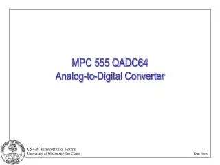
MPC555 Interrupt Example:Periodic Interrupt Timer (PIT) 16-bit counter: counts down to 0. On zero, raise an interrupt. • Driven by a clock from an internal oscillator (usually 4MHz) • divided by 4 (or at 1 MHz): 1 microsecond counting interval. • Use following registers • PICSR: Periodic Interrupt Control & Select Register • PITC: PIT Counter • PITR: Periodic Interrupt Timer Register
PICSR: Periodic Interrupt Control & Select Register 0x2F C240 PInterrupt Enable 0: disable interrupt 1: enable interrupt Interrupt levelfor PIT 1 2 3 4 5 6 7 0 PIRQ PS PIE PITF PTE 9 10 11 12 13 14 15 8 PITFreeze 0: no effect 1: disable decrement counter if internal signal FREEZE is asserted PITEnable 0: enable decrement counter 1: disable decrement counter PIT Status 0: no PIT int asserted 1: PIT int asserted
0 15 PITC PITC: PIT counter PITC: PIT Counter 0x2F C244 • PIT Time-out period = (PITC+1)/(PIT Frequency); • assume 1MHZ oscillator • PIT Period = 1/(1MHz) = 1 microsecond Put 33000 in PITC to get 33 milliseconds interrupt period.
PITR: Periodic Interrupt Timer Register If you want to read the current PIT count to estimate time to next PIT interrupt? 0x2F C248 0 15 16 31 PIT Reserved PIT: Leftover (current) count in PIT counter Writes to PITR have no effect: read only.
PIT Block Diagram PTE PISCR[15] PITC 16-bit Modulus Counter Clock Disable pitrtclkclock PS PISCR[8] PITinterrupt PIE PISCR[13] PITF PISCR[14]
PIT Initialization .equ USIU_BASE_UPPER 0x2f .equ PICSR_OFFSET 0xc240 .equ PITC_OFFSET 0xc244 .equ PITR_OFFSET 0xc248 ; r4 base address of SIU regs lis r4, USIU_BASE_UPPER ; set PISCR bits: PIRQ=08, PS=PS, PIE=1, PITF=0, PTE=1 ; so flag is cleared, interrupt is enabled, timer is ; enabled, and level is assigned li r0,0x0805 sth r0,PICSR_OFFSET(r4) ;PITC = 33000 = 0x80e8 and store it in PITC li r5, 0x80e8 sth r5, PITC_OFFSET(r4) ;in order to read PITR lhz r6, PITR_OFFSET(r4)
PIT Initialization (corrected) .equ USIU_BASE_UPPER 0x2f .equ PICSR_OFFSET 0xc240 .equ PITC_OFFSET 0xc244 .equ PITR_OFFSET 0xc248 ; r4 base address of SIU regs lis r4, USIU_BASE_UPPER ; set PISCR bits: PIRQ=08, PS=PS, PIE=1, PITF=0, PTE=0 ; so flag is cleared, interrupt is enabled, timer is ; enabled, and level is assigned li r0,0x0804 sth r0,PICSR_OFFSET(r4) ;PITC = 33000 = 0x80e8 and store it in PITC li r5, 0x80e8 sth r5, PITC_OFFSET(r4) ;now enable PIT: PTE = 1 lhz r0, PICSR_OFFET(r4) ori r0, r0, 0x1 sth r0, PICSR_OFFSET(r4)