Interrupt
Interrupt. Interrupts of 8051. Introduction 8051 Interrupt organization Processing Interrupts Program Design Using Interrupts Timer Interrupts Serial Port Interrupts External Interrupts Interrupt Timings. Interrupt.

Interrupt
E N D
Presentation Transcript
Interrupts of 8051 • Introduction • 8051 Interrupt organization • Processing Interrupts • Program Design Using Interrupts • Timer Interrupts • Serial Port Interrupts • External Interrupts • Interrupt Timings
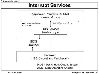
Interrupt • An interrupt is the occurrence of a condition--an event -- that cause a temporary suspension of a program while the event is serviced by another program (Interrupt Service Routine ISR or Interrupt Handler). • Interrupt-Driven System-- gives the illusion of doing many things simultaneously, quick response to events, suitable for real-time control application.
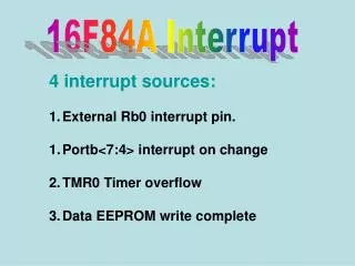
8051 Interrupt Organization • 5 interrupt sources: 2 external, 2 timer, a serial port • 2 programmable interrupt priority levels • fixed interrupt polling sequence • can be enabled or disabled • IE (A8H), IP (B8H) for controlling interrupts
Enabling and Disabling Interrupts IE (Interrupt Enable Register A8H) • Bit Symbol Bit Address Description (1=enable, 0=disable) • IE.7 EA AFH Global enable/disable • IE.6 - AEH Undefined • IE.5 ET2 ADH Enable timer 2 interrupt (8052) • IE.4 ES ACH Enable serial port interrupt • IE.3 ET1 ABH Enable timer 1 interrupt • IE.2 EX1 AAH Enable external 1 interrupt • IE.1 ET0 A9H Enable timer 0 interrupt • IE.0 EX0 A8H Enable external 0 interrupt Two bits must be set to enable any interrupt: the individual enable bit and global enable bit SETB ET1 SETB EA MOV IE,#10001000B
Interrupt Priority (IP, B8H) • Bit Symbol Bit Address Description (1=high, 0=low priority) • IP.7 - - Undefined • IP.6 - - Undefined • IP.5 PT2 BDH Priority for timer 2 interrupt (8052) • IP.4 PS BCH Priority for serial port interrupt • IP.3 PT1 BBH Priority for timer 1 interrupt • IP.2 PX1 BAH Priority for external 1 interrupt • IP.1 PT0 B9H Priority for timer 0 interrupt • IP.0 PX0 B8H Priority for external 0 interrupt • 0= lower priority, 1= higher priority, reset IP=00H • Lower priority ISR can be interrupted by a high priority interrupt. • A high priority ISR can not be interrupted.
Interrupt Flag Bits Interrupt Flag SFR Register & Bit Position ------------------------------------------------------------------------------ External 0 IE0 TCON.1 External 1 IE1 TCON.3 Timer 1 TF1 TCON.7 Timer 0 TF0 TCON.5 Serial port TI SCON.1 Serial Port RI SCON.0 Timer 2 TF2 T2CON.7 (8052) Timer 2 EXF2 T2CON.6 (8052) • The state of all interrupt sources is available through the respective flag bits in the SFRs. • If any interrupt is disabled, an interrupt does not occur, but software can still test the interrupt flag.
Polling Sequence • If two interrupts of the same priority occur simultaneously, a fixed polling sequence determines which is serviced first. • The polling sequence is External 0 > Timer 0 > External 1 > Timer 1 > Serial Port > Timer 2
Program Design Using Interrupts • I/O event handling: • Polling: main program keeps checking the flag, waiting for the occurrence of the event. Inefficient in some cases. • Interrupt-driven: CPU can handle other things without wasting time waiting for the event. Efficient, prompt if ISR is not so complex. Suitable for control application. • I/O processor: dedicated processor to handle most of the I/O job without CPU intervention. Best but most expensive
Processing Interrupts • When an interrupt occurs and is accepted by the CPU, the main program is interrupted. The following actions occur: • The current instruction completes execution. • The PC is saved on the stack. • The current interrupt status is saved internally. • Interrupts are blocked at the level of the interrupt. • The PC is loaded with the vector address of the ISR • The ISR executes. • The ISR finishes with an RETI instruction, which retrieves the old value of PC from the stack and restores the old interrupt status. Execution of the main program continues where it left off.
Interrupt Vectors • Interrupt vector = the address of the start of the ISR. • When vectoring to an interrupt, the flag causing the interrupt is automatically cleared by hardware. The exception is RI/TI and TF2/EXF2 which should be determined and cleared by software. Interrupt Flag Vector Address System Reset RST 0000H (LJMP 0030H) External 0 IE0 0003H Timer 0 TF0 000BH External 1 IE1 0013H Timer 1 TF1 001BH Serial Port RI or TI 0023H Timer 2 TF2 or EXF2 002BH
8051 Program Design Using Interrupt ORG 0000H LJMP MAIN ORG 000BH ; T0 ISR entry point LJMP T0ISR ORG 0030H ;above int vectors MAIN: . . T0ISR: . ; Timer 0 ISR . RETI ;return to main
Timer • The 8051 has two timers/counters, they can be used either as • Timers to generate a time delay • Event counters to count events happening outside the microcontroller • Both Timer 0 and Timer 1 are 16 bits wide • Since 8051 has an 8-bit architecture, each 16-bits timer is accessed as two separate registers of low byte (TLx) and high byte (THx)