Download
1 / 53
570 likes | 709 Vues
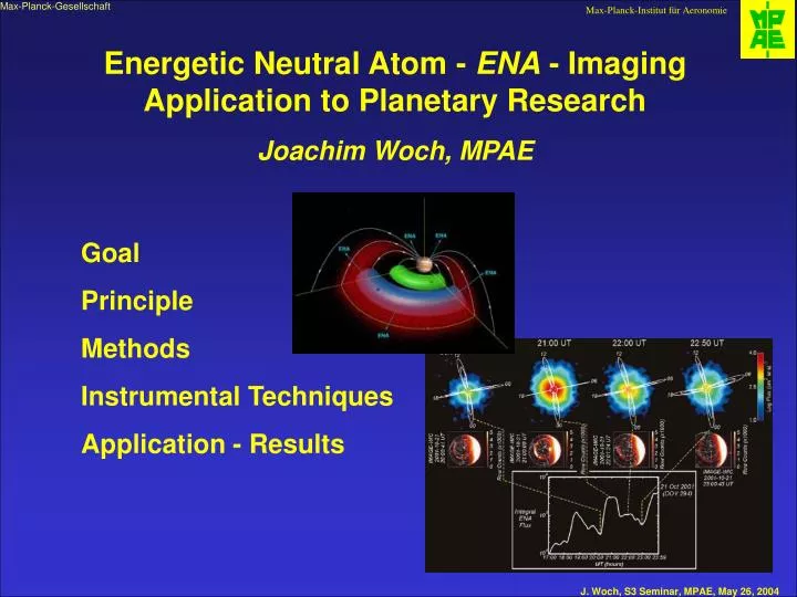
Energetic Neutral Atom - ENA - Imaging Application to Planetary Research Joachim Woch, MPAE. Goal Principle Methods Instrumental Techniques Application - Results. view on plasma processes in a high-density, collisional, light emitting environment.

E N D
Energetic Neutral Atom - ENA - ImagingApplication to Planetary ResearchJoachim Woch, MPAE Goal Principle Methods Instrumental Techniques Application - Results
view on plasma processes in a high-density, collisional, light emitting environment ENA Imaging – What For ?GOAL: Making plasma processes visible by monitoring the evolution of space plasma processes on a global scale Sometimes nature is friendly!
ENA Imaging – What For ?‘Imaging’ of Plasma Processes But most often NOT ! most plasmas in the solar system are low-density, proton dominated not sufficient photons to image
Studying Space Plasma Objects / ProcessesThe traditional way our concept of the best-studied plasma object in the solar system after more than 40 years of in-situ and ground-based observations
‘Imaging’ of Plasma Processes – The RealitySingle Point Observations of Magnetospheric Tail Processes
‘Imaging’ of Plasma Processes – The RealityMultiple point observations of ring current injections
‘Imaging’ of Plasma Processes – The Realityatmosphere and its aurorae as screen of magnetospheric processes
Studying Space Plasma Objects The Traditional Way • we are using • in-situ observations, mostly single-point • ground-based observation • remote-sensing of auroral displays • to study a huge, highly complex, dynamical system • in this way: • a global continuous monitoring of the evolution of the system is not easy to achieve
First of all: Do not take serious ‚Energetic‘ means anything above a neutral at rest Energetic Neutral Atom – ENA – Imaging
ENA Imaging – The Principle The co-existence of an energetic charged particle population (solar wind, magnetospheric plasma) and a planetary neutral gas leads to interaction, e.g., through charge-exchange: A+(energetic) + P(cold) A(energetic) + P+(cold) Little exchange of momentum → conserve velocity ENA are not influenced by E- and B-fields; they travel on straight ballistic path like a photon Directional detection of ENAs yields a global image of the interaction and allows to deduce properties of the source populations. • ENA production mechanism in space plasmas • Charge - exchange reaction with atmospheric / exospheric gases • Sputtering of planetary atmospheres • Backscattering from the planetary atmospheres (ENA albedo) • Sputtering from planetary surfaces • Ion neutralization / sputtering on dust particles • Recombination (CMI)
ENA Imaging – The PrincipleIn Other Words ... Energetic ions in a planetary magnetosphere (environment) interact with cold neutral atom populations through charge exchange collisions to produce energetic neutral atoms: The charge exchange collision involves little exchange of momentum, so that an ENA moves off from the collision point on a ballistic trajectory, with initial velocity equal to that of the parent ion immediately before the collision. The ENAs can be sensed remotely since they are no longer confined by the magnetic field as the parent ions were. → ions’ velocity distribution is preserved in the ENA distribution → composition is preserved → Thus, the ENA imaging technique enables quantitative, global-scale measurements of energetic ion populations from a remote observing point.
ENA Imaging – Interpretating the ImageA Mayor Challenge ~ sufficient for ENA Imaging beyond 10 Re
ENA Imaging – Interpretating the ImageA Mayor Challenge The main challenge facing ENA image science is to retrieve the underlying parent ion distribution from the ENA images. The directional ENA flux (Jena) at a point in space represents an integral along the chosen line-of-sight of the product of the hot ion flux toward the observation point (jion(r,v, t)), the cold neutral density (nneutral(r,t)), and the charge exchange cross section. That is, where r is the location along the line-of-sight at which the charge exchange interaction occurs, v is the ion vector velocity at the instant of the interaction, and t is time. Ion distributions are obtained by relating the remotely observed differential directional ENA flux (jENA) to the path integrated source intensity, and mapping this to the equatorial plane under the assumptions of gyrotropy and conservation of the first adiabatic invariant. This inversion problem is not well constrained from a single observation point.
ENA Imaging – Interpretating the Imagein other words ... Interpretation of images is difficult and severely model-dependent For a magnetospheric ENA image the emission regions are optically thin. Therefore, the image is a 2-D projection of the 3-D emission structure in the magnetosphere. Interpretation of the image requires constraining the position of the emissions along the line-of-sight by the known physics of the magnetosphere (e.g. Liouville‘s theorem constraining the particle phase space density distribution along the magnetic line of force). Analogous to medical x-ray imaging (3-D optically thin body collapsed into a 2-D plane). Interpretation only possible based on prior understanding of anatomy Way-Out (in future): multipoint imaging constrains models and parameter space; optical thin nature becomes distinct advantage allows tomographic reconstruction (CAT) of spatial distributions of plasmas
ENA Imaging – How to do it ?Measurement Techniques it‘s tough ! ENAs are tenuous and have to be measured against a `foreground´ of charged particles and UV photons → imposes difficulties even when doing `White Light Imaging´ ENAs are not influenced by em-fields → How to do spectral analysis ?
ENA Imaging InstrumentsThe Recipe step 1: prevent ions and electrons to enter the instrument → electric and magnetic collimator deflection systems step 2: reduce UV and EUV → foils, gratings step 3: convert neutral particle into ion → ionizing foils, grazing incidence on surfaces step 4: perform spectral, mass analysis → E and/or B fields, TOF system, E-PHA step 5: perform imaging → direction-sensitive detection (MCP, SSD) conserve velocity and directional information and combine it with a high geometric factor !
ENA Imaging InstrumentsThe Principle step 2: reduce UV and EUV → foils, photon absorbing surfaces step 3: convert neutral particle into ion → ionizing foils, grazing incidence on surfaces step 4: perform spectral, mass analysis → E + B fields, TOF system, SSD step 5: perform imaging → direction-sensitive detection (MCP, SSD)
Schematics of a real ENA InstrumentASPERA for MEX and VEX crystalline surface with high photon absorption, high electron yield, high conversion efficiency with which neutrals loose or capture electrons e.g. tungsten energy range several 10 eV to 10 keV can distinguish H from O moderate imaging capabilities
Schematics of a real ENA InstrumentINCA/Cassini and HENA/Image velocity, trajectory, energy, and mass of ENAs in the 10-500 keV energy range The HENA sensor consists of alternately charged deflection plates mounted in a fan configuration in front of the entrance slit; three microchannel plate (MCP) detectors; a solid-state detector (SSD); two carbon-silicon-polyimide foils, one at the entrance slit, the other placed just in front of the back MCP; and a series of wires and electrodes to steer secondary electrons ejected from the foils (or the SSD) to the MCPs.
Schematics of a real ENA InstrumentMENA/Image IMAGE's Medium Energy Neutral Atom (MENA) imager is a slit-type imager designed to detect energetic neutral hydrogen and oxygen atoms with energies ranging from 1 to 30 keV. The instrument determines the time of flight and incidence angle of the incoming ENAs; from these it calculates their trajectory and velocity and generates images of the magnetospheric regions from which they are emitted. The imager consists of three identical sensor heads mounted on a data processing unit (DPU). velocity, trajectory, (and mass H from O) of ENAs in the 1-10 keV energy range
ENA Image Inversions Validation in Earth’s Magnetosphere
Observing Substorm Particle Injections into the RC the traditional way 3 spacecraft the ENA way 1 spacecraft
Observing Substorm Particle Injections into the RCTemporal monitoring with ENA Imaging
ENA Imaging of other planet’s magnetospheresIt’s on its way – INCA/Cassini is arriving at Saturn • imaging the magnetospheric plasma • its interaction with • the solar wind • the planet‘s atmosphere • the moon Titan • the dust rings
ENA Imaging – Further ApplicationMeasuring Neutral Exospheres and Tori measured derived known known
ENA Images of a neutral gas nebula surrounding Jupiterfrom INCA/Cassini during the Jupiter flyby Krimigis et al.. Discovery of a magnetospheric neutral wind extending more than 0.5 AU from Jupiter: • Hot quasi-isotropic component • Cold component : neutrals escaping from Io’s plasma torus, following charge exchange and having a corotation speed of ~75 km s-1, confined close to the equatorial plane
raw ENA 140Rj INCA-ENA Images – Evidence for a Europa Torus 50–80 keV ENA images of Jupiter’s magnetosphere, revealed two distinct emission regions: the upper atmosphere of Jupiter a torus of emission residing just outside the orbit of Jupiter’s satellite Europa n ~ 40 cm-3 raw ENA 800Rj deconvoluted ENA Image confirmed by in-situ observation in the Europa torus Mauk et al. Lagg et al.
Titan’s exosphere interaction with Saturn’s magnetosphere •Titan’s orbit places it, most of the time, within Saturn’s magnetosphere. •Titan's nitrogen-rich atmosphere is subject to direct magnetospheric interaction, due to its lack of a significant magnetic field. • Energetic ions in the magnetosphere occasionally will undergo a charge exchange collision with cold neutral atoms from the upper Titan atmosphere, giving rise to the production of energetic neutral atoms. • The coexistence of energetic ions and cold tenuous gas in the Saturn/Titan system makes this system particularly suitable for magnetospheric imaging via energetic neutral atoms.
ENA Imaging at Mars A Case of non-magnetic solar wind – planet interaction MarsExpress since 01/2004
ENA Imaging at Mars Atmospheric Escape at Mars Absence of planetary magnetic field leads to important differences between Mars’ and Earth’s atmospheric escape and energy deposition processes upper atmosphere at Mars not protected by magnetic field direct interaction of shocked solar wind with exosphere massive erosion through ionisation and tailward convection; sputtering
ASPERA-3 on MarsExpress Imaging plasma and energetic neutral atoms near Mars Objective: To measure solar wind scavenging : The slow “invisible” escape of volatiles (atmosphere, hydrosphere) from Mars. Question: Is the solar wind erosion the prime reason for the present lack of water on Mars?
Solar wind scavenging of the martian atmosphere Planetary wind = Outflow of atmosphere and ionosphere (cometary interaction) ASPERA will do global imaging and in-situ measurements of: Inflow — solar wind Outflow — planetary wind using: Energetic neutral atom cameras and plasma (ion+electron) spectrometers Solar wind Planetary wind ≈100 ton/day Note: Mars (and Venus) are planets lacking a strong intrinsic magnetic field (umbrella) => dehydration.
ENA AT MARS IMAGING OF PLANETARY OXYGEN
ENA AT MARS IMAGING OF PLASMA BOUNDARIES Bößwetter et al.: Plasma boundaries at Mars
ENA Imaging at Venus Atmospheric Escape at Venus VenusExpress: Launch 2005 Absence of planetary magnetic field leads to important differences between Venus’ and Earth’s atmospheric escape and energy deposition processes upper atmosphere at Venus not protected by magnetic field direct interaction of shocked solar wind with exosphere massive erosion through ionisation and tailward convection; sputtering; em-processes with topside ionosphere Large similarities Venus / Mars The Ionosphere of Venus: A complex structure of plasma clouds, rays, and holes formed by the interaction with the solar wind
ENA Imaging at Mercury’s Magnetosphere A case of direct solar wind magnetosphere - exosphere - surface interactions Messenger, BepiColombo Launch 2011
ENA Imaging – Further ApplicationDetecting Neutral Particle Populations Direct Measurements of the LISM Our solar system moves through the surrounding Local Inter Stellar Medium (LISM) It consists of a mixture of charged particles, with embedded magnetic fields, and a neutral component, mainly uncharged hydrogen and helium atoms. As the interstellar plasma and the solar wind, cannot penetrate each other because of their embedded magnetic fields, a boundary layer, the Heliopause, is formed, The Heliopause is assumed to exist at a solar distance of about 100 AU. The Heliopause prevents the interstellar plasma from entering into the solar system. Therefore, little is known about the details of the LISM, and the knowledge so far is mainly based on remote sensing techniques. However, the neutral component of the LISM, not shielded by the magnetic fields can penetrate into the inner solar system and is available for in-situ observation.