Download
1 / 46
480 likes | 1.11k Vues
Hayward Gordon XCS. Screw Centrifugal Pumps Training Session – ?????? WWTP. XCS Screw Centrifugal Pump. Training Outline. Introduction Description of Pump Pump overview (design features). Where are the pumps being used? Review of pump performance curve. Maintenance - Lubrication.

E N D
Hayward Gordon XCS Screw Centrifugal Pumps Training Session – ?????? WWTP
Training Outline • Introduction • Description of Pump • Pump overview (design features). • Where are the pumps being used? • Review of pump performance curve. • Maintenance - Lubrication. • 7. Maintenance – Mech. seal or Packing. • Maintenance – Pump end. • Maintenance – Powerframe. • Maintenance – Impeller clearance adjustment. • Installation / Start-up Checklist. • Trouble Shooting.
INTRODUCTION • H.G. entered the process pump business in the early 1960’s with the development of the small frame ANSI pumps. • In the 1970’s we designed our TORUS line of recessed impeller pumps, the cantilever pump line including the design of the slurry wet ends and the first sulfur pumps. • In the late 1980’s we started on our next major design phase with the development of the XCS screw centrifugal pumps. • At the end of the 1990’s we started on the CHOPX design.
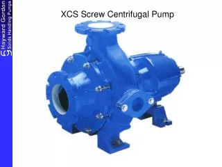
Description of Pump What is a XCS screw centrifugal pump? A screw centrifugal pump is a unique design that combines the advantages of a screw pump and a centrifugal pump. The result, is a pump that can efficiently handle thick sludges, large or stringy solids, shear sensitive fluids and delicate materials. The XCS impeller, is a single vane construction, with hydraulic sections. The front action acts like a positive displacement screw, gently drawing fluid into the pump. The single vane slowly accelerates the fluid through the screw section into the centrifugal pump section, where the pressure head is developed. The long, single channel impeller produces high flow at relatively low total dynamic heads.
XCS Screw Centrifugal Pump Independent seal housing Adjustable suction cone Heavy duty powerframe Non-clogging Impeller Back pull-out
****Example: Sludge Pumps – Qty. 2 Equip.# Pump model XCS8D-VDP s/n Pump has grease lubricated bearings, John Crane Type 1 single mech. seal, direct driven by a 10 hp 1150 rpm motor. Duty point of 1,500 usgpm @ 20’ tdh
XCS Screw Centrifugal Pump Typical Performance Curve
Maintenance • Inspection Port • for impeller clearance • adjustment
Maintenance – Lubrication Grease Lubricated Bearings *** All grease lubricated bearings are filled with grease at the factory and do not require filling before starting. - Use a Lithium base NLG1 Grade 2 grease to replenish the bearings every 2400 hours of continuous operation. Avoid over greasing the bearings. - Use a contact type thermometer mounted on the powerframe or bearing housing to measure the bearing temperature. Do not “test” by hand as 120 F and higher may feel hot but bearing temperatures up to 140 F are normal, depending on ambient temperatures. Grease lubricated bearings may be safely operated up to at least 170 F. Higher temperatures may be experienced during initial run-in period of approximately 36 operating hrs. - A sudden temperature increase indicates the possibility of damage that requires checking.
Maintenance – Mechanical Seal • *** See Manufacturer’s drawing and instructions for maintenance and • lubrication requirements. • Causes of failures and leakage between seal faces: • Scored or worn seal faces. • Gland bolted up unevenly. • Stationary insert face not perpendicular to shaft axis. • Binding seal ring. • Wobbling rotating seal ring. • Cracked or broken stationary insert. • Shaft run out through stuffing box. • Foreign matter between seal faces. • Loose or released set screws. • Spring compression lost. • Mechanical seal improperly applied or installed. • Improper materials of construction for the environment or temp. • Differential or system pressure too high for seal.
Maintenance – Packing • Repacking Stuffing Boxes • Remove nuts and gland. • 2. Remove all packing rings and lantern ring with packing hook. Be • sure to replace packing rings located on both sides of lantern ring. • Clean box, shaft and sleeve. • 4. Install packing. • *** Replace base ring with every second packing change. Frequent need • to repack indicates deeply grooved shaft sleeve that should be • replaced.
Maintenance – Packing • Packing Procedure • 1. Spin shaft by hand to see there is no binding. • 2. Rub thin film of oil on shaft and in stuffing box. • 3. “S” twist rings sideways to install packing. DO NOT pull rings straight • straight out over shaft. • Insert needed number of rings, below lantern ring, staggering joints • 90 degrees and seating each ring individually. • Insert lantern ring (line up with tapped hole from seal connection). • Insert remaining packing rings, staggering joints 90 degrees, and • and insert split gland.
Maintenance – Packing • Setting New Packing • Using wrench, tighten gland nuts snug, back off, and re-tighten finger • tight. • Start pump. • Check stuffing box for overheating. Shut down to cool, if necessary. • Gradually pull up gland by turning gland nuts alternately, one-quarter • turn at a time, as packing wears from operation. Never tighten gland • excessively. • An additional ring of packing may be added to box after gland has been • taken up full travel. Repack stuffing box when packing gland has again • been taken up full travel.
Maintenance – Packing Setting New Packing – Continued CAUTION! With new packing, generous and steady initial leakage must be maintained. Over a period of 4-6 hours, the gland may be gradually tightened to achieve A stuffing box leakage rate of 30 to 60 drops a minute. Monitoring is Recommended during this start-up period to ensure that the lubrication is Not cut off as the packing warms up and expands. If this occurs, the gland Must be loosed to restore the leakage. Turn sealing liquid on before pump is primed and leave it on as long as liquid is in pump. Use sealing fluid to prevent air leakage, if a prime is to be held when pump is stopped. Do not try to prevent air leakage by tightening gland unless definite measures are taken to be sure of re-adjustment before starting.
Maintenance – Packing Setting New Packing – Continued CAUTION! The packing must not be allowed to run dry – even for short periods. Scoring of the shaft sleeve may result that will cause premature failure of the packing and will prevent proper sealing until a new sleeve is installed.
Maintenance – Packing • Causes of Packing Failure & Excessive Leakage • Packing not properly installed. • Packing not suitable for pressure and temperature. • Packing subject to attack by liquid pumped. • Inner rings not seated properly, outer rings carrying entire load. • Foreign matter (dirt) in stuffing box causing rapid scoring of shaft • sleeve
Maintenance Motor pedestal Pump pedestal
Maintenance – Pump End • Disassembly of Pump Wet End • The back pull-out feature of these pumps allows the complete powerframe • rotating element to be removed without disturbing suction or discharge • piping. For all arrangements the volute and piping will remain in place. • Remove D-flange motor from motor pedestal. • Remove motor pedestal from pump assembly. • Remove bolts holding powerframe assembly to the volute, then follow • disassembly instructions for liquid end.
Maintenance – Pump End • Liquid End – Mechanical Seal Pumps • Remove carriage bolts, lock washers and nuts. Swing up or to the side • powerframe / seal housing assembly from volute. • Put powerframe / seal housing assembly on workbench. • Remove half coupling from shaft. • Remove volute o-ring. • Remove impeller screw, lock washer, impeller and key. • 6. Remove seal housing from powerframe. • Remove gland nuts & washers and slide seal gland clear of seal hsg. • Remove mechanical seal. • 9. Remove shaft sleeve, o-rings and slinger.
Maintenance – Pump End • Liquid End – Packed Pumps • Remove carriage bolts, lock washers and nuts. Swing up or to the side • powerframe / stuffing box assembly from volute. • Put powerframe / stuffing box assembly on workbench. • Remove half coupling from shaft. • Remove volute o-ring. • Remove impeller screw, lock washer, impeller and key. • 6. Remove stuffing box from powerframe. • 7. Remove gland nuts, washers, split gland, packing, lantern ring and • base ring. • 8. Remove shaft sleeve, o-rings and slinger.
Maintenance – Powerframe • Grease Lubricated • Remove bearing housing hardware and press shaft/bearing assembly from powerframe and remove shims. • Remove inboard retaining ring, press inboard bearing and grease shield from shaft. • Remove bearing cap hardware & slide outboard bearing cap from shaft. • Remove lip seal from bearing cap. • Remove both bearing housing o-rings. • Slide bearing housing off outboard bearings. • Remove bearing nut and lock washer. • Press outboard bearings and grease shield from shaft. • Remove lip seal and if applicable inboard seal plate c/w lip seal from powerframe.
Maintenance – Impeller Front Clearance adjustment • Pump with suction cone and no liner • Assuming pump has been in operation lock out motor and isolate pump from system (close suction & discharge valves). Drain fluid in pump (pressure in line will be eliminated). • Verify clearance between impeller and cone with feeler gauge. Access for this is through the inspection port on the volute. Refer to O&M manual for acceptable clearance. • Use split shim set to obtain correct clearance. Shims are located between suction cone and volute. To gain access to shim set, loosen bolts holding suction cone to volute only. • 4. Confirm correct clearance with feeler gauge. • 5. Re-tighten bolts from suction cone to volute. • 6. Try rotating shaft by hand, it should rotate freely.
Maintenance – Impeller Front Clearance adjustment • Pump with suction cone and adjustable liner • Assuming pump has been in operation lock out motor and isolate pump from system (close suction & discharge valves). Drain fluid in pump (pressure in line will be eliminated). • Loosen the hex nuts on each adjustable liner screw. • Carefully screw in each adjustable screw until the impeller touches the cone (the shaft cannot turn) being sure to adjust each screw the same amount. • Back off each of the adjustable screws so that the impeller clearance matches that listed in the O&M manual. This is confirmed by measuring the clearance with a feeler gauge through the inspection port on the volute. • Tighten the hex nuts ensuring the adjustable screws stay stationary. • Try rotating shaft by hand, it should rotate freely.
Maintenance – Parts Inspection Ball Bearings Replace if damaged. If they are dirty, flush with clean kerosene or carbon tetrachloride, dray and coat with machine oil. Lip Seals Inspect and replace if worn or damaged. Lip seal is held by press fit in bearing caps. Shaft Check for bent shaft. Bearing and lip seal seats must be in perfect condition. Replace if necessary. Shaft Sleeves Sleeve surface in stuffing box must be smooth and free of grooves. Replace if grooved.
Maintenance – Parts Inspection Impeller and Suction Cone (or liner) If these items show excessive wear due to abrasion or corrosion and performance cannot be restored, it must be replaced. Packing Replace if worn or damaged. Mechanical Seal Replace if worn or damaged *** All parts must be clean before reassembly. This is especially important at retaining ring grooves, threads, gasket surfaces and bearing lubrication areas. Remove burrs with fine emery cloth especially on shaft surface.
Installation/Start-up Checklist • Shipment • Was there any damage in transit? • b) Were all items received?
Installation Start-up Checklist • 2. STORAGE • Has equipment been protected from the elements? • Was equipment subject to flooding? • Have storage instructions been followed?
Installation Start-up Checklist • 3. INSTALLATION • Is grouting under base properly compacted and free of voids? • Is grouting of the non-shrink type? • Have proper anchor bolts been used? • Have the bolts been properly tightened? • Are the suction/discharge pipes properly supported and anchored near the pump? • Were flanges connected to piping without stress? • Are seal water lines properly installed? • Are accessory items, RTD’s, bearing temp detectors, vibration sensors etc., mounted and properly installed?
Installation Start-up Checklist • INSTALLATION Continued … • i) If oil lubricated bearings has the lubricant been added? (Grease lubricated pumps are factory greased). • Are all safety labels in place? • VFD’s – has the VFD been properly set up and have all settings been checked with the pump/motor manufacturer?
Installation Start-up Checklist • 4. ALIGNMENT • Has alignment of driver to pump been measured (refer to table in O&M manual for maximum allowable Parallel and Angular misalignment)? (List readings) • Belt drives – has belt tension been checked (refer to O&M manual)?
Installation Start-up Checklist • 5. ROTATION • Has the rotation of the drives been checked for correctness? • Has the coupling/sheave been turned, by hand, to assure free rotation of pump and motor?
Installation Start-up Checklist • 6. SYSTEM • Has the system been checked to insure that it is free of foreign matter and purged of air, which could be damaging to the pump? • Is suction valve fully open? • Is discharge valve 25% open (open to 100% immediately after start-up)? • Is liquid available to the pump? • Has assurance been obtained from responsible parties that all piping is secure and that the routing of flow has been established and is correct? • For VDP pumps: Has the pump seal chamber been vented?
Installation Start-up Checklist • 7. START-UP (Record as many as possible) • Performance data – refer to operating requirements of this project. • Suction and discharge pressure gauge readings (list at various duty points)? • Re. Packed Pumps: Packing drips/minute after break in period? • Re. Sealed Pumps: Seal water pressure (psi)? • Other observations.
Installation Start-up Checklist • 8. SAFETY • Have all safety/warning labels been read and understood?
Trouble Shooting • Speed too Low • - Incorrect wiring ~ Check electrical connections of motor. • Vibration – Noise • Misalignment between pump and motor ~ Realign unit. • Loose foundation bolts ~ Tighten bolts, take care not to distort base. • Defective grout ~ Remove grout and regrout base. • Bent shaft ~ Inspect shaft, replace if bent. • Binding rotating equipment ~ Ensure pump rotates freely. • Pumps too much liquid, head lower than rated ~ Restrict discharge by • partly closing discharge valve. • Cavitation on the suction side due to lower NPSH available ~ Raise • suction/liquid level. • Closed suction or discharge valve ~ Open suction or discharge valve. • Blockage in suction or discharge piping ~ Remove blockage from • piping.
Trouble Shooting • Overheating Bearings • Misalignment between pump and driver ~ Realign unit. • Bent shaft ~ Inspect shaft, replace if bent. • Binding rotating equipment ~ Ensure pump rotates freely. • Excessive lubricant ~ See O&M manual for recommended bearing • lubrication. • Defective or contaminated bearings ~ Clean bearings and lubricate, • replace if worn.
Trouble Shooting • No Discharge Flow • Pump not primed ~ Prime pump. • Speed too low ~ Check voltage and frequency. • Required discharge head too high ~ Reduce head, increase speed or • possibly install larger diameter impeller. Take care not to overload the • motor. • Suction lift higher than pump rating ~ Raise suction/liquid level or • lower pump. • Impeller or volute is blocked ~ Clear blockage. • Suction port is blocked ~ Clear blockage.
Trouble Shooting • Not Enough Discharge Flow • Excessive air leaks in suction pipe or stuffing box ~ Tighten all flange • bolts. Supply stuffing box with liquid. • Speed too low ~ Check voltage and frequency. Increase pump speed. • Required discharge head too high ~ Reduce head, increase speed or • possibly install larger diameter impeller. Take care not to overload the • motor. • Suction lift too high ~ Raise suction/liquid level or lower pump. • Mechanical defects (I.e. worn impeller) ~ replace defective parts. • Foot valve too small ~ use larger foot valve • Impeller or volute is blocked ~ Clear blockage. • Suction port is blocked ~ Clear blockage. • Insufficient NPSH available ~ Raise suction/liquid level or lower pump. • Wrong rotation direction ~ Reverse any 2 leads on 3-phase motor.
Trouble Shooting • Not Enough Pressure • Speed too low ~ Provide proper voltage and frequency to motor. • Increase pump speed, take care not to overload motor. • Too much air or gas ~ Vent casing. • Damaged impeller ~ Replace impeller. • Wrong rotation direction ~ Reverse any 2 leads on a 3-phase motor.
Trouble Shooting • Loss of Prime • Leak in suction line ~ Tighten suction line flange bolts. • Loss of sealing liquid to stuffing box ~ Ensure sealing liquid reaches • stuffing box. • Suction lift too high ~ Raise suction/liquid level or lower pump. • Too much air or gas in liquid ~ Vent case. • Insufficient NPSH available ~ Raise suction/liquid level or lower pump.
Trouble Shooting • High Power Consumption • Speed to high ~ Lower pump speed. • Pumps too much liquid, head lower than rating ~ Restrict discharge by • partly closing valve. • Specific gravity or viscosity of liquid pumped higher then rated ~ Reduce • pump speed. Reduce liquid specific gravity or viscosity. • - Bent shaft ~ Inspect shaft, replace if bent. • Binding rotating element ~ Ensure pump rotates freely. • Seal/packing gland too tight ~ Loosen gland nuts.