Download
1 / 28
280 likes | 354 Vues
This proposal suggests utilizing the 433 MHz channel for 802.15.4f PHY and MAC alterations, offering advantages such as lower interference, cost-efficiency, and optimal data throughput. The document outlines channel parameters, modulation techniques, data rates, link budget considerations, tag blink rates, and location determination mechanisms. It aims to contribute to the standard development process of 802.15.4f.

E N D
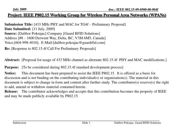
Project: IEEE P802.15 Working Group for Wireless Personal Area Networks (WPANs) Submission Title: [433 MHz PHY and MAC for TG4f – Preliminary Proposal] Date Submitted: [11 July, 2009] Source: [Dalibor Pokrajac] Company [Guard RFID Solutions] Address [#8 – 1600 Derwent Way, Delta, BC, V3M 6M5, Canada] Voice:[604-998-4018], E-Mail:[dalibor.pokrajac@guardrfid.com] Re: [Response to 802.15.4f Call For Preliminary Proposals] Abstract: [Proposal for usage of 433 MHz channel as alternate 802.15.4f PHY and MAC modifications.] Purpose: [To be considered during 802.15.4f standard development process] Notice: This document has been prepared to assist the IEEE P802.15. It is offered as a basis for discussion and is not binding on the contributing individual(s) or organization(s). The material in this document is subject to change in form and content after further study. The contributor(s) reserve(s) the right to add, amend or withdraw material contained herein. Release: The contributor acknowledges and accepts that this contribution becomes the property of IEEE and may be made publicly available by P802.15. Dalibor Pokrajac, Guard RFID Solutions
433 MHz PHY and MAC for TG4fPreliminary Proposal Dalibor Pokrajac, Guard RFID Solutions
Why 433 MHz PHY? • Avoid busy 2.4GHz channel • Thousands and tens of thousands Tags must coexist in small area • Interference with Wi-Fi, Bluetooth, Zigbee, wireless phones, etc. • Low cost • Low energy per bit transmitted / received (increased battery life) • Narrow band = low silicon complexity (low cost and power consumption) • Low infrastructure deployment cost (no “tuning” or “calibration”) • Satisfactory RF performance • Low pathloss • Optimal data throughput • Optimal location accuracy for majority of applications • Seamless Indoor and Outdoor use • Acceptable frequency band in most regions • Not true ISM band worldwide, but close to it Dalibor Pokrajac, Guard RFID Solutions
433 MHz Channel Parameters Dalibor Pokrajac, Guard RFID Solutions
Frequency Band 580 kHz 540 kHz f [MHz] 433.05 433.63 434.21 434.79 433.92 • Band: • 433.05 MHz - 434.79 MHz • 1.74MHz width • Channels: • Single channel centered at 433.92 MHz • Potentially 3 channels available at 250 kb/s • Channel Bandwidth: 540 kHz Dalibor Pokrajac, Guard RFID Solutions
Modulation • Minimum Shift Keying (MSK) • Continuous phase FSK Reduced non-linear distortion • Frequency difference between “1” and “ 0” = ½ data rate (modulation index is always 0.5) • Signals are orthogonal and minimal distance more compact spectrum • Trade-off between ISI and side-lobe suppression • Low Inter Symbol Interference (compared to GMSK) but higher side lobes (less efficient use of spectrum) • The available 433 MHz channel is wide enough to tolerate this trade-off Q 01 11 I 00 10 Dalibor Pokrajac, Guard RFID Solutions
Data Rate • Data rate has impact on • PER • Communication distance • Battery life • 1 = RX sensitivity for 1.2 kbps = -110 dBm • 2 = +10dBm transmit power, 20 bytes PDU, 3V battery, ITX = 25 mA • Tradeoff between RX sensitivity, energy consumption, tag density 250 kb/s as optimal Data Rate Dalibor Pokrajac, Guard RFID Solutions
Link Budget • Noise Power N = kTB = 1.38x10⁻²³[J/K]x 290 [K] x 540,000 [s-1] = 2.16 * 10-12 [mW] N = -116 dBm • Receiver Noise Figure NF = 10 dB (assume low cost receiver) • Receiver Noise Floor RNF = N + NF = -106 dBm • Probability of bit error (BER = 10-4) Eb/No = 8 dB = 6.3 • Signal To Noise Ratio SNR = (Eb/No) * (R/B) = 6.3 x (250 [kbps] / 540 [kHz]) = 4.64 [dB] - Received Power Prx = RNF +SNR = -106 + 4.64 = -101 [dBm] • Propagation Loss Lfs = 20 * log10 (4 * π * D / λ); D = 30 m Lfs (30m) = 54 [dB] D = 100 m Lfs (100m) = 65 [dB] Dalibor Pokrajac, Guard RFID Solutions
Link Budget (cont’d) • Transmit antenna Gain Gtx = - 20 [dB] • Receive antenna Gain Grx = 0 [dB] • Transmitter Power Ptx = 10 [dBm] Fade Margin = Ptx – Prx – Lfs + Gtx + Grx Fade Margin (30 m) = 10 – (-101) – 54 + (-20) + 0 FM (30m) = 37 [dB] Fade Margin (100 m) = 10 – (-101) – 65 + (-20) + 0 FM (100m) = 26 [dB] • Tags with larger antenna will have better Fade Margin • Tag Readers with NF < 10 dB will have better Fade Margin Very small Tag antenna (0.75 inch diameter). Dalibor Pokrajac, Guard RFID Solutions
Tag Blink Rate • Estimated requirements: • Proposed Blink Rates for 433 MHz PHY: • Dynamic Blink: • 10 sec • 60 sec • Static Blink: • 10 min • 60 min • A Tag could have both Blink Rates (static and dynamic) or only one Dalibor Pokrajac, Guard RFID Solutions
Location Determination Mechanism • Received Signal Strength (RSS) • Received signal is measured and compared to a noise floor • Due to pathloss and fading, signal strength is reverse proportional to distance (non-linear) • X-Y-Z coordinates of Receivers must be known • Multiple receivers receive and forward the same packet to CPU • Tag location is derived based on triangulation (relative RSSI) • Absolute RSSI is unreliable method for location determination due to fading, multipath, tolerances in receive sensitivity and transmit power Dalibor Pokrajac, Guard RFID Solutions
Location Accuracy • RSSI based triangulation • Multipath compensation through statistical analysis (signal received by multiple nodes ) • Sub 3 meter accuracy • Majority of applications don’t need better accuracy • Low infrastructure cost • No need for system tuning and calibration) • Location is available within few seconds of Tag blink • Data must be collected from Tag Readers • Network delays during data collection • Portal detection through alternative technologies (LF, IR, US): • Instant portal detection at very low power consumption cost (3-10 µW for “always on” operation) • Accurate Portal to Portal differentiation even when they are near each other • Precise room location (exact side of the wall) Dalibor Pokrajac, Guard RFID Solutions
RFID/RTLS within 802.15.4 TX Only Uni-directional communication New 802.15.4f CCA before TX RFID / RTLS Tags Protocol and Tag complexity, cost and size Non-Beacon Network Bi-directional communication Beacon Network • Transmit Only tags for most sensitive applications • Many applications do not need 2-way communication or even CCA • Bidirectional Tags where data storage is needed or high link reliability • Traditional 15.4(e) communication Classic 802.15.4 Dalibor Pokrajac, Guard RFID Solutions
Bi-Directional Tags • Compliant to “IEEE Std 802.15.4 – 2006” • FFD Tag Reader • RFD Tags • MAC Frame changes as per pending 15.4e • Additional MAC Frame changes as per 15.4f (if any) • Beacon Network • Applications with relatively small number of Tags • Applications where communication reliability is important • Non-Beacon Network • Tag decides when to transmit data (Blink) • Acknowledged or unacknowledged Dalibor Pokrajac, Guard RFID Solutions
CCA before TX “Listen Before Talk” mechanism Clear Channel Assessment (CCA) performed before every transmission to avoid collisions Back-off mechanism as described in 802.15.4 Tag Blink Period Tag Blink Period BO CCA BO CCA BO CCA TX Packet BO CCA TX Packet Number of CCA+BO Slots depends on collision rate Back-off RX Dalibor Pokrajac, Guard RFID Solutions
CCA-TX Simulation Results • Assumptions: • Tag state machine model Dalibor Pokrajac, Guard RFID Solutions
CCA-TX Simulation Results (cont’d) • Note:Simulation results courtesy of Hongbo Guo, University of British Columbia • Highlighted (Bemin, Bemax) looks reasonably good, but… Dalibor Pokrajac, Guard RFID Solutions
A flaw in “CCA before TX” • Tag antenna gain is usually significantly lower than Tag Reader antenna gain (10 - 20 dB or even more) • 20 dB in link budget equals lots of distance! • Tags cannot hear majority of other Tags that Tag Reader can • 10 db difference in antenna gain Tag can hear ~ 25% other Tags • 20 db difference in antenna gain Tag can hear ~ 5% other Tags • Energy spent on CCA is largely wasted! These 2 Tags CANNOT hear each other but Tag Reader can hear both Tag RX range Tag Reader Tag Reader RX range These 2 Tags can hear each other Dalibor Pokrajac, Guard RFID Solutions
TX Only Tags • Variation of P-Aloha (“Double P-Aloha”) • Low protocol efficiency but minimized power consumption and code complexity • Collision “avoidance”: • Tags send redundant, randomized packets to compensate for collisions when Blink periods align • Tag timing is based on imperfect time keeping to allow Blink Windows to slide over time and Blinks drift apart Tag Blink Period Tag Blink Period Blink Window Blink Window Blink Window TX Packet Imperfect Blink Period timing Multiple, identical packets, randomized within Blink Window Dalibor Pokrajac, Guard RFID Solutions
Collision Rate of Double P-Aloha • Probability of reception of P-Aloha follows Poisson distribution formula: • Packets cannot overlap (overlap = collision), therefore: • Channel loading (G): • Success rate for each packet reception (Sp): • Success Rate for each Tag ID reception (Sid): • Some real life examples (systems with less than 1,000 and 5,000 Tags): Mrepeat = Number of Packets in a Blnk Ntag = Number of Tags Tid = Packet length T blink = Blink period Tid = 600 µs T blink = 10s Mrepeat = 3 Ntag = 1,000 Tid = 600 µs T blink = 60s Mrepeat = 1 Ntag = 5,000 Sid = 0.95 Sid = 0.97 Dalibor Pokrajac, Guard RFID Solutions
Successful Tag ID Reception Probability of Double P-Aloha • Tblink = 600 µs (20 byte PDU @ 250 kbps) • Depending on expected Tag density for particular application, Mrepeat and Tblink should vary (defined by Tag class) sa Tblink = 10s Mrepeat = 3 Tblink = 60s Mrepeat = 1 Dalibor Pokrajac, Guard RFID Solutions
PPDU Very similar to classic 15.4 PPDU Proposal: Add Synch bytes for byte synchronization PHY overhead: 7 bytes 4 Octets 2 Octet 1 Octet Variable Preamble Synch Length R PSDU Synchronization Header PHY Header PHY Payload (MAC Frame) Dalibor Pokrajac, Guard RFID Solutions
MPDU General MAC Frame format • Changes to 15.4 MAC • Source Address Length change (0 / 2 / 8 Octets 0 / 3.5 / 6 / 8 Octets) • Total MPDU length is 9.5 / 11 / 14 bytes (depending on Tag ID) • Total PPDU length is 7+9.5/11/14 bytes PPDU = 16.5 / 18 / 21 bytes • At 250 kbps PPDU = 528 / 576 / 672 [µs] 2 Octets 1 0/2 0/2/8 0/2 0/2/8 0/5/6/10 Variable 2 Frame Control Sequence Number Dest. PAN ID Dest. Address Source PAN ID Source Address Security Header Payload CRC 2 Octets 1 1 0/3.5/5/8 Variable 2 Frame Control Sequence Number Dest. PAN ID Tag ID Payload CRC Dalibor Pokrajac, Guard RFID Solutions
MPDU Field Description • Frame Control: Allows compatibility with classic 15.4 MAC • Sequence Number: Data traffic reconstruction • Tag Class: Defines MAC and PHY parameters • Tag ID: • Based on EUI-64 MAC address • 28 bit: Extension Identifier (when Company ID = 36 bits) • 40 bit: Extension Identifier (when Company ID = 24 bits) • 64 bit: Full EUI-64 address • Payload: defined by Tag manufacturer • Specific Tag type within the Tag Class • Sensor data (includes alternate location methods: LF, IR, ultrasound,…) • Includes alternate ID numbers • CRC: Polynomial of 16th degree Dalibor Pokrajac, Guard RFID Solutions
Tag Classes • Tag Classes are needed because one size doesn’t fit all! • Parameters to define Tag Class: • PHY • MAC variation (TX Only, Beacon Enabled, Non-Beacon) • Transmit power (ERP) • Blink Rate • Data Rate • Alternative location mechanism or sensor data Dalibor Pokrajac, Guard RFID Solutions
433 MHz Coexistence • Within the band • Regulatory limits (e.g. FCC) restrict in-band interference with other 433 MHz devices • Tag to Tag interference is mitigated through redundant packet transmissions (Double Pure Aloha), CCA or CSMA • With 802 devices • There is no interference with any of existing 802 devices • With Licensed devices • This band is ISM band or de-facto ISM band worldwide • There is no interference with any of licensed devices Dalibor Pokrajac, Guard RFID Solutions
433 MHz Compliance • North America • FCC 15.231(e) and RSS-210 • Field strength: 4400 uV/m @ 3m • 10 sec blink rate • FCC 15.240 • Field Strength: 55,000 uV/m @ 3m • Europe, Africa • Region 1 ISM Band • EN 300 220 • Max ERP: 10 mW@1% or 1mW@10% duty cycle • Asia • SRRC (China) implementation matches the EU radio regulations. • Max ERP: 10 mW, occupied bandwidth < 400 kHz • Singapore: IDA TS SRD:2008 • Max ERP: 10 mW • Australia / New Zealand • AS/NZS 4268:2003 • Countries throughout the world permit usage of the 433 MHz band at various ERP levels and duty cycles Dalibor Pokrajac, Guard RFID Solutions
Thank You! Dalibor Pokrajac, Guard RFID Solutions