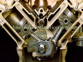


Background Jet Engine Combustion
E N D
Presentation Transcript
Improved Design of a Self-Actuated Valve for Pressure Gain Pulsejet CombustorsKyle Gaiser, Case Western Reserve University, Department of PhysicsDr. Daniel Paxson, NASA Glenn Research Center Dr. James T’ien, Case Western Reserve University, Department of Aerospace Engineering___________________________________________________________________________________________________________________________________________________________________________________________________________________________________ Project Overview Pulsejet reed valves have notoriously short life spans. When subject to the extreme temperatures, pressures, and high rates of impact characteristic of the pulsejet tests performed at NASA Glenn, the valves last approximately fifty seconds. This is detrimental to pulsejet performance and hinders research efforts. Below are two figures depicting a failed valve (left) and the valve head (right) The project’s objectives are threefold: 1. Global dynamics: understand the valve’s motion and correlation to pressure variation. 2. Impact dynamics: understand causes of failure and predict cycles to failure. 3. Mitigation Techniques: evaluate geometry, valve materials, and valve arrangement, and provide suggestions for better designs. Background Jet Engine Combustion A jet engine operates on a Brayton cycle, which incorporates three engine components: the compressor, the combustor, and the turbine, as illustrated below. The compressor and combustor increase the fluid pressure and temperature, respectively, resulting in hot gases from which useful energy is extracted by the turbine or utilized in the nozzle for additional thrust. The efficiency of the Brayton cycle is determined by the product of the compressor and combustor pressure ratios, also known as the overal pressure ratio, PB/PA: PB/PA – overal pressure ratio; γ– specific heat ratio; η - efficiency A larger pressure ratio increases efficiency, resulting in more useful work and thrust. However, a 4 – 8 percent pressure loss across the combustion chamber alone is typical of current jet engines. One method to remedying this problem is through pressure gain combustion. • Impact Dynamics Model • An energy based model is used to predict the life of the valve. The impact energy is calculated from the velocity of the valve upon impact, which is obtained from the Global Dynamics model. This energy is also the area under the stress-strain curve, which is shown below. By interpolation, the valve’s stress and strain is determined from the area underneath the stress-strain curve. • Given basic material properties of the valve, the following equations are estimated and plotted. • 1. Ramberg-Osgood Equation for stress-strain curve: • 2. Manson-Coffin Equation (blue) and Universal • Slopes Method (red) for cycles to failure: • Graph 2 depicts two methods used for predicting the life of the valve. While literature says the Universal Slopes curve is typically more accurate, the Manson-Coffin method works better for the spring steel valve used in the pulsejet. Nevertheless, the two methods combined give a range of confidence, within an order of magnitude, of the actual number of cycles to failure. Global Dynamics Model To model the valve’s motion, a computer simulation simplifies the valve to a spring covering an inlet, as shown below on the left. The motion is complex, governed by the valve’s material properties, the mass flow rate, and pressure variations on the valve. Applying Bernoulli’s equation and Newton’s second law, a set of coupled equations is numerically integrated. The figure below and to the right illustrates the relationship between the valve’s position, in blue, and velocity, in green, obtained by the model. To validate the program, a high speed pressure transducer and an infrared fiber optic sensor are placed next to the valve during a test of the pulsejet. The data is used to compare the experimental pressure and motion of the valve to that of the computer model. Pressure Gain Combustion and Pulsejets Pressure gain combustion is a method that increases the pressure across the combustion chamber, resulting in higher efficiency engines. This can be achieved via a high frequency, resonant, pulsed combustion process such as that utilized in pulsejets. The pulsejet is a mechanically simple engine with one moving part: a reed valve. This valve controls the injection of the air-fuel mixture into the combustion chamber, opening and closing at the same high frequency as the combustion. The valve’s movement is completely self-actuated; it is governed by the mass flow and pressure variations on of the valve. • Future Work • Account for high temperature fatigue on the valve • Develop mitigation techniques for future valve designs Acknowledgments Dr. John Lewandowski, Dr. Kenneth Singer, Dr. Mark De Guire, Dr. Robert Mullen