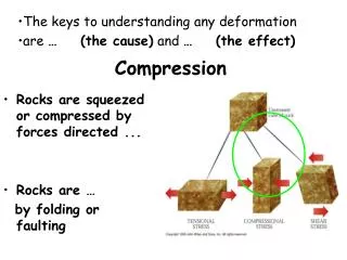
LONGITUDINAL STIFFENERS ON COMPRESSION PANELS
LONGITUDINAL STIFFENERS ON COMPRESSION PANELS Chai H. Yoo, Ph.D., P.E., F. ASCE Professor Emeritus Department of Civil Engineering Auburn University CIVL 7690 July 14, 200 9 History ● The most efficient structural form is truss

LONGITUDINAL STIFFENERS ON COMPRESSION PANELS
E N D
Presentation Transcript
LONGITUDINAL STIFFENERS ONCOMPRESSION PANELS Chai H. Yoo, Ph.D., P.E., F. ASCE Professor Emeritus Department of Civil Engineering Auburn University CIVL 7690 July 14, 2009
History ● The most efficient structural form is truss with regard to its weight-to-strength ratio provided that all other conditions are equal. Old section of NY Metro Subway system, Tower crane post and arms, Space station, New Orleans Super dome, etc.
Brooklyn Bridge, New York • Designed by Roebling, Opened in 1883
Auburn University Highway Bridges, Past, Present, and Future George Washington Bridge, New YorkDesigned by Amman, opened in 1931
History ● For containment type structures maintaining two or more separate pressure or temperature zones, continuous barriers, membranes, plates and shells, are required. Aircraft fuselage, Dome roof, Submarines, etc.
History ● When the loads (both transverse and longitudinal) are small→membrane, i.e., placard medium→plates heavy→stiffened plates topic of discussion
BACKGROUND AASHO Standard Specifications for Highway Bridges, 9th ed., 1965 adopted for the first time the minimum moment of inertia of the longitudinal stiffener: where There was no further stipulation as to the correct value for k.
BACKGROUND For composite box girder compression flanges stiffened longitudinally and transversely, AASHTO requites the minimum moment of inertia of the longitudinal stiffener: It is of interest to note that the absence of a length parameter of the longitudinal stiffener in both AASHTO equations. A longitudinal stiffener attached to the compression flange is essentially a compression member.
BACKGROUND It was found that an old bridge, (curved box girder approach spans to the Fort Duquesne Bridge in Pittsburg) designed and built before the enactment of the AASHTO criteria on longitudinal stiffeners, did not rate well for modern-day traffic, despite having served for many years.
BACKGROUND Despite the practicing engineers’ intuitive realization of the unreasonableness of the equations, they are still in force in both AASHTO Standard Specifications for Highway Bridges, 17th ed. (2002) and AASHTO LRFD Bridge Design Specifications, 4th ed. (2007) with a limitation imposed on the number of longitudinal stiffeners not to exceed “two.”
BACKGROUND In a relatively short period of time, there were a series of tragic collapses occurred during the erection of the bridges Danube in 1969 Milford Haven Bridge in Wales in 1970 West Gate Bridge in Australia in 1970 Koblenz Bridge in Germany in 1971
BACKGROUND These tragic collapses drew an urgent attention to steel box girder bridge design and construction. Some of the researchers, primarily in the U.K., responded to the urgency include: Chatterjee Dowling Dwight Horne Little Merrison Narayana
BACKGROUND Although there were a few variations tried, such as Effective Width Method Effective Length Method these researchers were mainly interested in “Column Behavior” of the stiffened compression flanges.
BACKGROUND Barbré studied the strength of longitudinally stiffened compression flanges and published extensive results in 1937.
BACKGROUND Bleich (1952) and Timoshenko and Gere (1961) introduced Barbré’s study (published in German) to English speaking world using the following model:
Consider the load carrying mechanics of a plate element subjected to a transverse loading ● Very thin plates depend on the membrane action as that in placards and airplane fuselages ● Ordinary plates depend primarily on the bending action ● Very thick plates depend on bending and shear action Our discussions herein are limited to the case of ordinary plate Elements (no membrane action, no shear deformation)
BACKGROUND It was known from the early days that stiffened plates with weak stiffeners buckle in a symmetric mode while those with strong stiffeners buckle in an antisymmetric mode. The exact threshold value of the minimum moment of inertia of the stiffener, however, was unknown.
Symmetric or antisymmetric buckling is somewhat confusing. It appears to be just the remnant of terminology used by Bleich. It is obvious that symmetric buckling implies column behavior and antisymmetric buckling implies plate behavior
It appears to be the case, at least in the earlier days, that the column behavior theory was dominant in Europe, Australia, and Japan while in North America, particularly, in the U.S., a modified plate behavior theory prevailed.
Japanese design of rectangular box sections of a horizontally curved continuous girder
In the column behavior theory, the strength of a stiffened plate is determined by summing the column strength of each individual longitudinal stiffener, with an effective width of the plate to be part of the cross section, between the adjacent transverse stiffeners.
It should be noted that in symmetric buckling (column behavior), the stiffener bends along with the plate whereas in antisymmetric buckling (plate behavior), the stiffener remains straight although it is subjected to torsional rotation.
Symmetric Mode Antisymmetric Mode
Hence, it became intuitively evident that in order to ensure antisymmetric buckling, the stiffener must be sufficiently strong.
A careful analysis of data from a series of finite element analyses made it possible to determine numerically the threshold value of the minimum required moment of inertia of a longitudinal stiffener to ensure antisymmetric buckling.
Symmetric Antisymmetric Critical Stress vs Longitudinal Stiffener Size
Selected example data are shown in the table. During the course of this study, well over 1,000 models have been analyzed.
Comparison of Ultimate Stress, Fcr (ksi) (Note: 1 in. = 25.4 mm; 1 ft = 0.305 m; 1 in4 = 0.416106 mm4; 1 ksi = 6.895 MPa)
Jaques Heyman, Professor emeritus, University of Cambridge, wrote in 1999 that there had been no new breakthrough since Hardy Cross published Moment Distribution method in 1931. • I disagree. • The most significant revolution in modern era is Finite Element method. Although the vague notion of the method was there since the time of Rayleigh and Ritz, the finite element method we are familiar with today was not available until in the late 1980s encompassing the material and geometric nonlinear incremental analysis incorporating the updated and/or total Lagrangian formulation.
Despite the glitter, Finite Element method is not a design guide. • Daily practicing design engineers need design guide in the form of charts, tables and/or regression formulas synthesizing and quantifying vast analytical data afforded from the finite element method. • There exist golden opportunities for engineering researchers to do just those contributions.
REGRESSION EQUATION Where
It was decided from the beginning of our study that we wanted to make sure that our stiffened compression flanges would buckle in an antisymmetric mode.
In the elastic buckling range of the width-to-thickness ratio, the critical stress of the plate is with
AASHTO divides the sub-panel between longitudinal stiffeners or the web into three zones by the width-to-thickness ratio: yield zone = compact transition zone = noncompact elastic buckling zone = slender
The regression equation for the minimum required moment of inertia of the longitudinal stiffener works equally well for the sub-panels in all three zones. It also works for horizontally curved box girders.
Longitudinal stiffener arrangement, AASHTO Longitudinal stiffener arrangement, Proposed
Japanese design of rectangular box sections of a horizontally curved continuous girder
Consider the moment of inertia about the axis parallel to the flange and at the base of the stiffener. Tee, WT9x25: A = 7.35 in2, tf = 0.57 in Is = 53.5+7.35(8.995-2.12)2 = 400 in4 Rectangle, d/t = 0.38(E/Fy)1/2 = 9.15 with Fy = 50 ksi for compact section: 9.15t2 = 7.35, t = 0.9 in, d=7.35/0.9 = 8.17 in Is = 0.9(8.17)3/3 =164 in4 Tee shapes are stronger than rectangles