Download
1 / 13
130 likes | 264 Vues
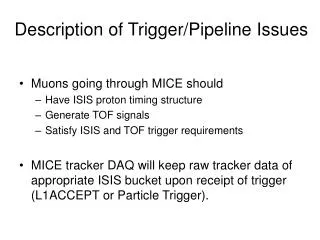
Description of Trigger/Pipeline Issues. Muons going through MICE should Have ISIS proton timing structure Generate TOF signals Satisfy ISIS and TOF trigger requirements

E N D
Description of Trigger/Pipeline Issues • Muons going through MICE should • Have ISIS proton timing structure • Generate TOF signals • Satisfy ISIS and TOF trigger requirements • MICE tracker DAQ will keep raw tracker data of appropriate ISIS bucket upon receipt of trigger (L1ACCEPT or Particle Trigger).
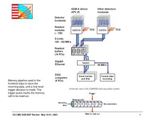
Description of Trigger/Pipeline Issues • Trigger formation from ISIS and TOF signals takes ~ 1000 ns. • When raw data arrive at AFE IIt boards, we don’t know immediately if this data corresponds to muon data. • Solution: • Store data from each ISIS bucket in pipeline putting data into pipeline at bucket period. • When trigger is received, keep and process data from particular pipeline slot corresponding to trigger formation time. Note: slot number or pipeline depth ~ (trigger formation time)/(bucket period) • Potential problems • Trigger formation time not multiple of proton bucket period • Proton bucket period varies from 345 ns to 324 ns over course of 1 ms wide spill
Start with ISIS bucket structure at end of spill with - bucket period = 324 ns - bucket width = 108 ns 1 2 3 4
Start with ISIS bucket structure with - bucket period = 324 ns - bucket width = 108 ns Suppose events A, B occur in bucket 1 at times tA= 50 ns, tB= 90 ns. A B 1 2 3 4
Start with ISIS bucket structure with - bucket period = 324 ns - bucket width = 108 ns Suppose events A, B occur in bucket 1 at times tA= 50 ns, tB= 90 ns. Assume it takes 1000 ns to form trigger. A B A B Trigger formation time = 1000 ns 1 2 3 4
Buckets are placed in pipeline: bucket 1 A B A B Trigger formation time = 1000 ns 1 2 3 4 Bucket 1 added to pipeline. 1
Buckets are placed in pipeline: bucket 2 A B A B Trigger formation time = 1000 ns 1 2 3 4 Bucket 1 added to pipeline. Bucket 2 added to pipeline. 1 2 1
Buckets are placed in pipeline: bucket 3 A B A B Trigger formation time = 1000 ns 1 2 3 4 Bucket 1 added to pipeline. Bucket 2 added to pipeline. Bucket 3 added to pipeline. 1 2 1 3 2 1
Buckets are placed in pipeline: bucket 4 Triggers for events A and B arrive before and after bucket 4 added to pipeline. This presents problem for setting pipeline depth for taking data out of pipeline. A B A B Trigger formation time = 1000 ns 1 2 3 4 Bucket 1 added to pipeline. Bucket 2 added to pipeline. Bucket 3 added to pipeline. Bucket 4 added to pipeline. 1 2 1 3 2 1 4 3 2 1
Buckets are placed in pipeline: bucket 4 Triggers for events A and B arrive before and after bucket 4 added to pipeline. This presents problem for setting pipeline depth for taking data out of pipeline. Before 4th bucket added to pipeline, pipeline depth needs to be set to 3 for event A. After 4th bucket added to pipeline, pipeline depth needs to be set to 4 for event B. A B A B Trigger formation time = 1000 ns 1 2 3 4 Bucket 1 added to pipeline. Bucket 2 added to pipeline. Bucket 3 added to pipeline. Bucket 4 added to pipeline. 1 2 1 3 2 1 4 3 2 1
Solution: Add delay to trigger. In this case, a delay between 80 ns – 296 ns results in necessary pipeline depth of 4 for any event in bucket 1. After 4th bucket added to pipeline, pipeline depth needs to be set to 4 for events A and B. Trigger formation delay = 80 ns A B A B Trigger formation time = 1000 ns 1 2 3 4 Bucket 1 added to pipeline. Bucket 2 added to pipeline. Bucket 3 added to pipeline. Bucket 4 added to pipeline. 1 2 1 3 2 1 4 3 2 1
What About Variable ISIS Bucket Period? Trigger formation time = 1000 ns • At beginning and end of spill, the trigger needs to be delayed so that the pipeline depth is 4 for any event occurring in bucket 1. • Adding trigger delay of 80 ns – 296 ns works at end of spill • Bucket period = 324 ns • Bucket width = 108 ns • Adding trigger delay of 150 ns – 380 ns works at start of spill • Bucket period = 345 ns • Bucket width = 115 ns
What About Variable ISIS Bucket Period? Trigger formation time = 1000 ns • Adding trigger delay of 80 ns – 296 ns works at end of spill • Bucket period = 324 ns • Bucket width = 108 ns • Adding trigger delay of 150 ns – 380 ns works at start of spill • Bucket period = 345 ns • Bucket width = 115 ns • Satisfying both constraints done be setting trigger delay between 150 ns – 296 ns. • Appropriate trigger delays can be determined for trigger formation times < ~3000 ns.