Download
1 / 74
740 likes | 928 Vues
Real Time Control of advanced scenarios for steady-state tokamak operation. Xavier LITAUDON CEA-IRFM, Institute for magnetic fusion research (IRFM) CEA Cadarache F-13108 St Paul Lez Durance. France e-mail: xavier.litaudon@cea.fr.

E N D
Real Time Control of advanced scenarios for steady-state tokamak operation Xavier LITAUDON CEA-IRFM, Institute for magnetic fusion research (IRFM) CEA Cadarache F-13108 St Paul Lez Durance. France e-mail: xavier.litaudon@cea.fr Courtesy: J.F Artaud, A. Bécoulet, S. Brémond, D. Campbell, J. Ferron, G. Giruzzi, C. Gormezano, E. Joffrin, S. H Kim, D. Mazon, D. Moreau, P. Politzer,T. Suzuki, T. Tala
OUTLINE TOWARDS REAL TIME PROFILE CONTROL ? • Challenges for continuous operation • continuous tokamak reactor operation • real time control requirement • Real time control of kinetic & magnetic energy • optimal profile for steady-state & MHD stable profiles • approaches to profiles control • Real time fusion D-T burn control • burn control with dominant bootstrap and a-heating ? • Control of core performance with the plasma facing components constrains • wall scenario compatibility issues • simultaneous control of core & edge
Optimisation of tokamak concept BT IP IC BP IP = Iinductive+ INon-Inductive • Long-Pulse Operation → IP = INon-Inductive • Non-Inductive Current Drive • Externally driven, e.g. waves injection • To drive 15MA on ITERrequires 150MW • 150MW coupled power requires ~ 1GW fusion • Internally driven Pression: bootstrap effect • Efficient reactor at high Q =Pfus/Padd relies on the optimisation of bootstrap current [e.g. Kikuchi M Nucl. Fusion 1990, Gormezano C ITER physics basis Nuc Fus 2007]
Challenges of continuous tokamak operation • Fully non-inductive regime • High confinement & bootstrap current • Real time control of kinetic & magnetic configuration close to operational limits with a large fraction self a-heating & bootstrap • Technology of Long Pulse Operation • Coils, Plasma Facing Components, Structure Materials, Heating &Current Drive systems, Diagnostics, data acquisition, fuel cycle… Worldwide research activity: physics, modelling, technology
Towards a continuous tokamak reactor DEMO ITER Tore Supra DD ~400s 0% 20% Q ~ 30 Continuous 80 to 90% 60-80% Q ~ 10 400-3600s 70% 10-50% A scientific and technical challenge JT60-SA JET Pfusion/Padd Q ~ 1 2s 10% 20% DD ~100s 0% >60% duration self-heating bootstrap Existence and control of a self-organised plasma state for continuous tokamak operation ?
Bpol Btor • Toroidal • bt = P/pBtor • pBtor=B2tor/2m0 • Poloidal • bp= P/pBpol • pBpol=B2pol/2m0 Basic standard tokamak parameters • Safety factor q • number of toroidal turns for one poloidal turn • Confinement • H=t/tscaling H~1 • tscaling = I R2 P-2/3 • Stability • q >1 • bN =bt/(Ip/aB) ≤ 3
stability limit low q95 limit bt [%] SS q95~4-5 Fusion gain optimisation Inductive q95~3 bp STEADY-STATE REACTOR : Optimisation of QDT & Bootstrap current QDT btt B2 • fusion power+ bootstrap • high bN , t , B • since bt bp (1+k2) b2N • Optimise shaping • Stability • -q & pressure • -wall stabilisation • Confinement Bootstrap optimisation Iboot/Ipe½ bp=e-½q bN
H-mode + internal transport barrier Plasma pressure L-mode H-mode Pedestal radius 0 1 Enhanced performance for non-inductive regimes
Towards Long Pulse Operation on ITER Inon-inductive/Ip Ibootstrap/Ip • Inductive operation • Q 10 Ip~15MA 400s • ‘Intermediate’ • Q ~5-10 Ip~12MA 1000s • fully non-inductive • Q~5 Ip~9MA 3000s • Active research activity • Integration of physics & technology 20% 7% 50% 20% 100% 50%
5 2 1 0 1 ITER STEADY-STATE OPERATION Steady-State operation at Q ~ 5 (Pa~Padd) with full non-inductive current drive + optimized current & pressure profiles q95~5 (9MA) at high k, d • Iboot/Ip50% • bN~3, H98(y,2) ~1.5 • nl~7x10¹⁹m-3 • Ti/Te ~ 1 • tD~3000s qo-qmin~0.5 qmin ~ 1.5-2.5 [Gormezano Nuc Fus 2007, Campell Pop (2001), Green et al PPCF 2003 & ITPA steady-state group]
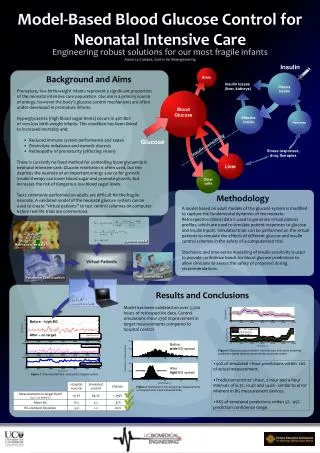
nHe/ne=6% t*He/ tE =5 Gyro-Bohm scaling bN=3.5 bN=2 CONTROL OF CORE CONFINEMENT IN STEADY-STATE ITER OPERATION ITER-AT: Ptot=73MW, Vloop=0 CRONOS-0D • Control of high confinement • for steady state: • DH/H~20% DQ/Q~50% (at Q~5) • favourable effect of density peaking while nHe/ne< 6% b0 ITER SS target b-0.9 [Litaudon PPCF 2006]
The decisive role of real time control • Bringing Fusion to its “Reactor Era” requires an innovative programme of“discharge mastering”, combining: • real time control of the magnetic/kinetic configuration (non-linear and time effects) • real time control of component integrity • high-level algorithms and control schemes • a consistent set of simulation tools: • first principles (“PFlops”) • integrated modelling (“CPU hours”) • fast simulators (“~ 10 ms”) [A. Becoulet & G.T. Hoang PPCF 2008 and Joffrin et al PPCF 2003 ]
Pol. Field Magnetization Burn termination Current Ramp Down Current Ramp Up Current Flat Top Breakdown Heating Control requirement: plasma scenario PF Reset And Recool Fusion Power Time(s) Plasma Current Inductive Flux D-T Fuelling Plasma Density a-particle Fraction Additional Power
Example of scenario: JET plasma JET #67687
Real Time plasma profile reconstruction(EQUINOX code) #57336 [Joffrin et al PPCF 2003, Joffrin et al PPCF 2007 ]
Plasma scenario : 15MA H-mode ITER scenario Tokamak simulation: free-boundary equilibrium (DINA-CH) & transport evolution (CRONOS) ITER S.H. Kim et al, PPCF 2009
[R. Buttery, EFPW 05] MHD Stability issues & real time control • Edge Localized Modes • Damage to Plasma Facing Components • Neo-classical tearing modes • Limiting pressure, risk of disruption • Resistive wall modes • Limiting pressure • Disruptions • Device safety • Fast particle modes • Limiting -heating, CD Necessity for Real Time feedback control & localized CD
PROFILE CONTROL REQUIREMENTS FOR STEADY-STATE OPERATION ITER • ITER SS operation above the no-wall limit • at ITER wall position, the marginal b is sensitive to details in q and pressure profiles • qmin~2.4,bN <3.85 • qmin~2.1,bN<2.6 P q r [Shimada et al NF 2004, Polevoi et al IAEA 2002]
ITER Heating & Current Drive actuators: FLEXIBILITY for profile Control 170 GHz 5 GHz 40-55 MHz 1MeV/D- ITER 33MW/CW 20MW/CW 20MW/CW 20MWCW
Control of a self-organised state ? • two time scale: fast (blue) & Slow (red) • a-heating dominant in burning reactor Actuators Plasma [Politzer et al NF 05]
PROFILE CONTROL REQUIREMENTS • Oscillation in confinement observed in steady-state tokamak plasmas limiting the fusion perfomance • Tore Supra* & DIII-D** (i) non-linear coupling between j & TjLH(j,T),jboot (j,T),c(j,T) (ii) non-linear interplay of heating, CD & MHDs<0, double tearing, ideal MHD limits … • ITER SS extra coupling via a-heating (i) non-linear coupling between j & Tjboot(j,T), c(j,T), Pa(T) (ii) non-linear interplay of heating, momentum, CD & MHD Pa(T),b limits, TAE (a-particles), … *Giruzzi et al PRL 03 **Politzer et al NF 05
LH Power (MW) Transformer flux (Wb) Te(R,t) Te(0) = 4.8 keV density (x1019m-2) Ti(0) =1.6 keV TORE SUPRA Neutron (x1010/s) Zeff ~2 Non-linear behaviour in non-inductive regime • oscillations of core electron temperature • non-linear interplay between q-profile, transport and heat sources (and MHD) Vloop=0 for 6 min, 1 GJ 2003 [Giruzzi PRL 03; Imbeaux PRL 06; Maget Nuc Fus 06]
Oscillation in bootstrap-dominated regime DIII-D Vl=0 (open transformer circuit) q95~10 0.7 Ip (MA) #119767 #119770 0.6 0.5 5 1 4 2 3 Time (s) • DW/W~50% • Iboot/Ip~85% • bN~bp~3.3 r r [Politzer et al NF 2005]
Non-optimal : narrow profiles and steep gradients Optimal ITB : broad profiles with moderate gradients MHD stability broad Jboot and Jtot broad ne for reduced impurity accumulation control of ITB radius, strength & width ACCESS TO HIGH bNOPTIMAL PROFILES ? ITB radius p=cst ITB width
Hybrid Reversed shear QDB 4 3 bN 2 1 2 4 6 p0/<p> High bN requires broad pressure profiles ITPA database • Stability limit improves with ITB radius and width* control of confinement & q-profile ? *Lao et al APS 99 [Sips IAEA 2004 , Litaudon et al PPCF 2004]
REAL TIME CONTROL OF KINETIC ENERGY JET • Operation close to the no-wall stability limit while avoiding disruptions • Real time control of neutral beam heating to match a neutron yield production • Similar results obtained on DIII-D, JT-60U t= [G. Huysmans et al., Nucl. Fusion, 1999, C. Gormezano et al FST 2008 ]
Control of electron temperature gradient • PLHCD to slow down q(r,t) • PNBI RT controlled by neutron • PICRHRT controlled by rs/LTe where LT= T/T • proportional-integral [Mazon, Litaudon, Moreau et al PPCF 02]
TORE SUPRA RT control of magnetic energy • feedback control for non-inductive operation: • Primary voltage Vloop-Vloop, ref • PLHCD Ip ref - Ip • n//-LHCD Liref- Li with Li b2q / b2q (a) • More recently* n//-LHCDHard X Ray width representative of LHCD absorbed & J profile [Wijnands Nuc Fus 1997, Litaudon PPCF 1998, *Joffrin Nuc Fus 2007]
RT control of minimum q, qmin DIII-D • Feedback control of qO or qmin during the plasma current ramp-up phase • Change of plasma conductivity through electron heating • ECRH or NBI • RT q-profile using MSE data [J. Ferron et al Nuc Fus 2006]
1.31.7 RT control of minimum q, qmin JT-60U • High-bp ELMy H-mode • Ip=0.8MA, Bt=2.5T, q95=5.8, ne=1.8x10¹⁹m-3, bp=1.2-1.5. • Off-axis LHCD control: • dPLHCD/dt=a(qmin,ref - qmin) • a=2MW/s • Without control • qmin down to 1.3 • Interaction j & Te • Requirement for T & J control interlocks by arcing N//=1.7 [Suzuki et al NF 2008]
Multi-Input-Multi-Output (MIMO) profile control All transfer functions are in matrix form Controller disturbance K(s) noise G(s) sensors actuators q(s) qtarget P(s) sensors plasma actuator dq(s)=K(s) dP(s) Controller dP(s)= G(s) dq(s) G(s)= gc[1 + 1/(tis)] K(0)inv First approach: control based on pseudo-inverse of the steady-state gain matrix [D. Moreau et al Nucl Fus 2003, D. Moreau et al Nucl Fus 2008]
RT q-profile control with off-axis LHCD in low b-phase • control in the prelude phase • "Model Based" control on 5 q-values • PLHCD is controlled to minimise (q-qtarget) in the least square sense • Access to various q-profiles [ D. Mazon et al PPCF 2003, D. Moreau et al Nucl Fus 2003]
setpoints start of control end of control undershoot RT q-profile control in high b-phase Multi-Input, multi-output control 3 actuators: LHCD, ICRH, NBI Model based SVD control: steady-state gain matrixdeduced from open loop experiments [D. Moreau et al Nucl Fus 2003]
q-profile Jplasma pressure pressure Internal Transport Barrier Jbootstrap bootstrap pressure Jext. Control of kinetic & magnetic profiles • non-linearly coupled profiles • two time scales • tres ~10s-100s • tE ~1-5s
ρ*T 1 0 x Control of kinetic & magnetic profiles ICRH q or i=1/q LHCD 1 0 x NBI modulations around a reference steady-state: Galerkin’s projection of 1/q and ρ*T [D. Moreau et al Nuc Fus 2008, T. Tala et al Nuc. Fus 2005]
Control of kinetic & magnetic profiles q profile and r*Te control The controller minimizes quadratic error: [Laborde et al., PPCF (2005), Moreau et al. Nuc Fus 2008]
Control of kinetic & magnetic profiles • Limitation of steady-state gain matrix approach: controller response slow during fast events • Development of an optimal control (time dependent model) q Measured Reference 1/q r*Te [Laborde et al., PPCF (2005), Tala et al Nuc. Fus 2005, Moreau et al Nuc Fus 2008]
Slow model: resistive time scale Fast model: momentum / thermal confinement time scale, t = e t e<<1 Fastcontroller : Two time-scale modelsslow: magnetic profiles, fast: kinetic profiles [Moreau et al Nuc Fus 2008] Slow controller : opt. feedback opt. feedback
x=0.1 x=0.2 x=0.3 x=0.4 x=0.5 x=0.6 x=0.7 x=0.8 x=0.9 x=1.0 Identification of a dynamical model Future: closed loop experiments 1/q(x) & V(x) • Generic approach: can be applied to any tokamak with any set of actuators and real-time measurements • Model identified on JET, JT-60U and DIII-D (on-going) Slow model for 1/q(x) x =0.5 x =0.4 x =0.6 x =0.5 x =0.7 x =0.8 x =0.6 x =0.9 x =0.7 N°70318 [Moreau et al Proc. 48th IEEE Conf. on Decision and Control China 2008]
Modelling of real time control of Te and q • q control @ 300s • Te control @ 400s • 4 actuators • transport model based on global confinement scaling law • real-time update of the static models ITER model based profile control (CRONOS) : 12MA hybrid mode ITER S.H. Kim et al, EPFL thesis No 4500 sub to PPCF
RT control in dominated bootstrap & a-heating regimes : open issues • existence of a stable and unique state with self-consistent pressure and current ? • control at high Iboot with PaPadd ? • rely mainly on q-profile control with minimum external CD? • pressure control requirements should be minimized • model based control? • strong requirements in terms of integrated transport modelling • ‘simulate’ in present day experiment a-heating with additional electron heating source • Experiments performed on JET & JT-60U to mimick a-heating in standard ELMy H mode regimes: how to extend to non-inductive operation ?
SIMULATION OF ALPHA PARTICLE PLASMA SELF-HEATING USING ICRH UNDER REAL-TIME CONTROL • ICRH applied in response to real-time measured plasma parameters (e.g. neutron rate) simulating the self-heating effect • part of the external heating plays the role of auxiliary heating • Demonstrate stable control of the simulated burn? [T. Jones, EPS 2001]
SIMULATION OF ALPHA PARTICLE PLASMA SELF-HEATING USING NBI UNDER REAL-TIME CONTROL [Takenaga et N Fus 2008]
Mimick the self-alpha heating and self-driven current in present day non-inductive experiments • Integrated fusion burn control experiment to prepare Long Pulse Operation on ITER & DEMO • ICRH/ECRH ‘mimic’ the a-power→ Pa and Pfus • ECCD/LHCD ‘mimic’ bootstrap→ fBoot > 50% • Remaining powers for control→Pcontrol → Qeff = Pfus/Pcontrol~ 5-20 • Could be tested on long pulse tokamaks : Tore Supra, JT-60SA, EAST etc … • “Proof of principle” through modelling using a simplified version of CRONOS, METIS • Combination of H&CD powers & density actuators are required for burn control: • Powers : fast and precise control • Density : slow and coarse control
Fusion burn simulation at high bootstrap fraction • high bootstrap burning plasma • a-heating mimicked using ICRH/ECRH • bootstrap mimicked using LHCD • Fuelling, Heating/CD feedback control • Equivalent fboot and Q Slow time scale
METIS : A tool for (burn) control simulation METIS work-flow organisation • Mixed 0D and 1D equations • Coupled to “Simulink” for real time control design • Fast dynamic simulation • ~ 1minutes for 300 time slices • 2s per time slice when coupled to Simulink • Included in the CRONOS suite to prepare integrated modelling [Artaud, Litaudon et al EPS 2008]
TORE SUPRA Modelling of Burn control with an L-mode confinement Control phase [Artaud, Litaudon et al EPS 2008]
TORE SUPRA Modelling of Burn control with an L-mode confinement Control phase • Burn control@ 10s • control feasible for range of Pa (gfus): • Q = 15 obtained • target is missed • system runs away Target: Q = 15 Target = 80 % • Add nD control (slow): widens the operational space available for burn control while minimizing the external heating sources.
TORE SUPRA Modelling of Burn control with ITB: Q~15 at fboot~70% at Vloop=0 Control phase