Catheter Guidewire Control System
240 likes | 263 Vues
Catheter Guidewire Control System. Derek Carlson & Caleb Anderson Advisors: Dr. Dempsey & Dr. Stewart. Contents. Caleb Anderson Overview of Catheterization Project Summary Overall Block Diagram Electroactive Polymer Polymer data Platinum vs. Gold Derek Carlson Motor Controller Board

Catheter Guidewire Control System
E N D
Presentation Transcript
Catheter Guidewire Control System Derek Carlson & Caleb Anderson Advisors: Dr. Dempsey & Dr. Stewart
Contents • Caleb Anderson • Overview of Catheterization • Project Summary • Overall Block Diagram • Electroactive Polymer • Polymer data • Platinum vs. Gold • Derek Carlson • Motor Controller Board • Stepper Motors • MATLAB progress • GUI • Updated Equipment List • Updated Foreseeable Difficulties • Schedule • Collaborative Progress w/ ME’s • Questions?
Currently requires the use of multiple guidewires Guidewire allows easy travel to area of blockage Catheter slides directly over guidewire Guidewire is then removed from vessel Overview of Catheterization www.forsythradiology.com www.amplatzer.com
Project Summary • Eliminate the need for different guidewires • Add precision control to the guidewire itself. • Add remote control to the guidewire simply by viewing the patient through a camera. • Control will be implemented using a joystick interfaced with MATLAB • A purchased controller board will run two stepper motors. • These stepper motors will be used for lateral motion and guidewire advancement. • A voltage reactive polymer will be used for precision tip control.
Electroactive Polymer • Material purchased from Environmental Robots, Inc by the Mechanical Engineering department • Responds to a DC voltage between -5V to 5V • +-5V results in an approximate 90 degree bend • Tip will be made of this material for precision control
Electroactive Polymer Characteristics • 2 kinds of polymer available • Platinum plated • Gold plated • We discussed testing procedures with the ME’s. • They returned voltage vs. curvature data for both types of polymer • Results
Polymer Run Times Platinum Plated Gold Plated
Platinum vs. Gold • Discussed results with ME students • Linearity issues • Runtime • Current Draw • Gold polymer was decided upon • Runtime was the largest reason • Slightly more linear as well • Did not have quite as large of an angle of deflection
Contents • Caleb Anderson • Overview of Catheterization • Project Summary • Overall Block Diagram • Electroactive Polymer • Polymer data • Platinum vs. Gold • Derek Carlson • Motor Controller Board • Stepper Motors • MATLAB progress • GUI • Updated Equipment List • Updated Foreseeable Difficulties • Schedule • Collaborative Progress w/ ME’s • Questions?
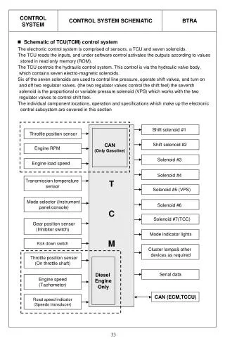
Motor Controller Board • Runs off of a USB-Serial driver • Dual supply mode • 2 motors connected draw roughly 1 amp when running • Controlled via MATLAB’s serial communication tools
Stepper Motors • Used for rotation and advancement of guidewire • (2) Jameco 8.4 V motors ordered • Suggested in Motor Controller Board documentation • Tested with Motor Controller board • Full functionality achieved • Total current draw = roughly 1 amp while running.
Stepper Motor Specs • Stepper Motor • Excellent for precision control • Can be operated in forward/reverse mode • Excellent torque/size ratio • Wide variety of supply voltages • Data sheet included • Dual shaft • Check for compatible power supplies • Step angle: 0.9 degrees • No. of phases: 2 • Drive System: Bipolar • Voltage(VDC): 8.4 • Phase resistance (Ω): 30 • Current (mA): 280 • Phase Inductance (mH): 25 • Detent torque(g-cm): 36 • Holding Torque(g-cm): 791 • Mounting hole space digonal (in.): 1.73 • Mounting hole (in.) 0.15 • Shaft diameter (in.): 0.155 • Shaft length(in.): .29 • Motor diameter (in.) 1.64 • Motor height (in.) 1.20 • Weight: 0.53 lbs.Jameco P/N 163395 MOTOR,STEP,8.4VDC,30 ohm.9deg,SHFT:.16"X.39"www.Jameco.com
MATLAB progress • Serial control of board completed in command-line form • Able to move motors independently • Can move motors a certain distance, and then have them return • All commands documented in BiStep controller board tested and functional
MATLAB GUI progress • Documentation of MATLAB GUIde environment • Basic GUI designed • Layout including buttons for advancement and retraction of guidewire • Command line interface for testing • Webcam function via command buttons • Webcam is functional separately, has not been implemented into GUI at this point because of speed of computer
Updated Equipment List • (2) 1 degree stepper motors (Jameco motors) • (1) Bistep Motor Controller Board • (1) Electroactive polymer tip • (1) Surgical Guidewire • (2) DC voltage sources • (1) PC USB Webcam • (1) Logitech Wingman Pro Attack 2 Joystick • (2) Metal pulley wheels with tight rubber belts • For gripping of the guidewire
Updated Foreseeable Difficulties • Polymer current draw was very high on large pieces (0.5 A) • Shielding will be a large problem inside of a human body. • UPDATE: Shielding solutions have been discussed and researched with the ME students. • Polymer functionality highly dependent upon moisture • This may be because we have worked with old and mistreated polymer samples. • UPDATE: New samples of polymer react better. There still is an issue of timing though. • Rotation and advancement of guidewire may be tricky to perform without damaging guidewire • UPDATE: Rubber wheel will be used to directly grip guidewire without damage.
Updated Schedule • Weeks 1-3 • Stepper motor MATLAB interface (Derek & Caleb) • Webcam MATLAB interface (Caleb) • RS-232 MATLAB interface (Derek) • Weeks 4-6 • GUI for user input (Both) • Develop polymer electrical characteristics (Both) • Detailed current draw calculations • Weeks 7-8 • Develop power electronics to actuate polymer (Derek) • Possible polymer shielding concerns (Caleb) • Weeks 9-10 • Stepper motor physical interface (Caleb) • Guidewire drive system (propulsion, rotation, etc.) (Derek) • Weeks 11-14 • Build test system (Both) • Finalize report & Presentation(Both)
Collaborative Progress • Meetings have been held with ME’s • Shielding concerns have been discussed • Medical grade wire for supply of power • Electrically conductive adhesive for connecting polymer to wire • Test system construction • New samples of polymer were ordered and received as of last week • These samples are for our exclusive use