Download
1 / 44
590 likes | 1.02k Vues
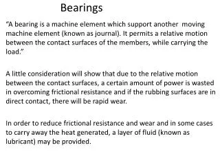
Bearings and Fluid-Induced Instability in Rotordynamics. Dr. Mehmet Sunar ME 562. Fluid Induced Instabilities. Fluid induced Instability is self-excited vibrations induced by internal mechanism that transfers rotational energy into the shaft as lateral vibrations.

E N D
Bearings and Fluid-Induced Instability in Rotordynamics Dr. Mehmet Sunar ME 562
Fluid Induced Instabilities Fluid induced Instability is self-excited vibrations induced by internal mechanism that transfers rotational energy into the shaft as lateral vibrations.
Properties of fluid induced instability • Created and controlled by fluid flow around the rotor. • Self excited. • Non synchronous. • Considered more destructive in fatigue view point.
Mathematical complexity due non-linearities in the bearing properties. Specially, in post instability conditions.
Modeling of bearing mechanical properties. Transient rotor response changes the fluid film bearing properties.
Average Circumferential Velocity Ratio. • Complex Dynamic Stiffness.
Fluid average circumferential velocity ratio It is the ratio of average fluid velocity to the average rotor velocity Lambda ( λ )= ū/ω
Eccentricity (e) • It is the distance from the center of bearing to the center of rotor. • Ratio=e/c. • Sometimes called radial deflection. e
Effect of eccentricity on stability in fluid film bearings • Higher eccentricity leads to lower fluid average velocity. • Lower fluid average velocity leads to better stability.
Bearing Stiffness • Higher eccentricity leads to higher stiffness. • Higher stiffness leads to better stability.
Complex dynamic stiffness • Total stiffness of fluid film bearings is considered to be complex and dynamic. • Real part is called direct stiffness • Imaginary part is called quadrature stiffness. • KT=KD+jKQ • KT=[KS-Mrω2]+j[ω(DS+D)-λDΩ] • Dynamic since it is speed dependant.
Threshold of instability • The speed at which fluid induced instability commences. (e.g. 1900 rpm)
Whirl. Forward precession. Usually starts earlier. Frequency holds a constant order of rotor speed. (dependent on rotor speed) Whip. Forward precession. Starts after whirl dies. (it may exist without being preceded by whirl) Frequency holds constant value (independent on rotor speed). Two types of Fluid Induced Instabilities
Fluid Induced Instability Whip Whirl Stable
Orbit= 2D shaft vibration FII Vibration symptoms: * Large Amplitude * Subsynchronous * Circular Orbit * Forward Precession
Experimental Setup • Experiments have been carried out at KFUPM MED Advanced Mechanics Lab. • Setup consists of • Bently Nevada rotor kit with fluid film bearing option. • Speed controller. • Oil pump. • Vibration pickups and ADRE software.
Typical experimental test results: Vibration spectrum
Shaft average centerline, clearance circle and average eccentricity ratio. Gradual concentricity. Zoomed run-up cascade. Instability threshold and frequency.
Threshold of instability change with oil pressure during start up
Threshold of instability change with oil pressure during shutdown
Disk Location (A) • Shaft Length (B) • Disk Unbalance (Unb)
Conclusions from experimental work • Higher flow rate of lubricating oil should raise the threshold of instability. • The unbalance has effect on instability.
System response at P=0.6 psi at 1800 rpm (Cont’d) F=11.72 Hz=703 cpm F=30 Hz=1800 cpm
System response at P=1.2 psi at 2300 rpm (Cont’d) F=13.67 Hz=820 cpm F=38.4 Hz=2300 cpm
Conclusions from theoretical work • Effect of Viscosity on the stability is expected. • Higher bearing pressure leads to higher threshold of instability.