Lecture 5 Combinatorial Logic
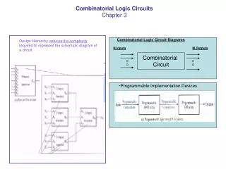
Lecture 5 Combinatorial Logic. Readings. Stalling,Computer Architecture & Organization, Appendix B, pp 701-726. Introduction. Combinatorial logic circuit – outputs are dependent only on the inputs. Assume the outputs respond immediately.

Lecture 5 Combinatorial Logic
E N D
Presentation Transcript
Readings • Stalling,Computer Architecture & Organization, Appendix B, pp 701-726.
Introduction • Combinatorial logic circuit – outputs are dependent only on the inputs. • Assume the outputs respond immediately. • In real circuits, propagation delays must be considered.
Specification (1) • List the outputs required (often only one) and the available inputs. • Draw up a truth table showing the value of the outputs for all possible inputs. • Label “don’t cares” with an X.
Specification (2) • Extend the table with a ‘column of products (‘ANDs’)’. • Extract those that correspond to a '1' in the output and ‘OR’ them together. • Simplify the Boolean function required to achieve the output.
A B P Parity Generator C Example3-Bit Parity Generator • Add an extra bit to data such that the number of 1s in the data is always odd. • Inputs - three inputs labelled A, B, C. • Output - a single output (P).
For ease of writing, from now on I will use X' to represent X. Change of Convention
3-Bit Parity Generator (continued) A B C P 0 0 0 0 1 1 0 0 1 0 2 0 1 0 0 3 0 1 1 1 4 1 0 0 0 5 1 0 1 1 6 1 1 0 1 7 1 1 1 0
A B C P 0 0 0 0 1 A'•B'•C' 1 0 0 1 0 A'•B'•C 2 0 1 0 0 A'•B•C' 3 0 1 1 1 A'•B •C 4 1 0 0 0 A•B'•C' 5 1 0 1 1 A •B'•C 6 1 1 0 1 A •B•C' 7 1 1 1 0 A •B •C 3-Bit Parity Generator (continued)
A B C P 0 0 0 0 1 A'•B'•C' 1 0 0 1 0 A'•B'•C 2 0 1 0 0 A'•B •C' 3 0 1 1 1 A'•B •C 4 1 0 0 0 A •B'•C' 5 1 0 1 1 A •B'•C 6 1 1 0 1 A •B •C' 7 1 1 1 0 A •B •C 3-Bit Parity Generator (continued)
Boolean equation in sum of products form: P = A • B • C + A • B • C + A • B • C + A • B • C 3-Bit Parity Generator (continued)
P = A • B • C + … A B P 3 C 3-Bit Parity Generator (continued)
a f b g e c d 7-Segment Decimal Decoder Example • Typical display for calculators, etc. • Seven segments in the shape of an ‘8’. • Turning specific segments on allows the display of all 10 decimal digits.
A 7-Segment Decimal Decoder B a b d e g c f C D So, what do we have? • How many outputs? • How many inputs?
Decimal number Binary Representation A B C D Segments a b c d e f g 0 0 0 0 0 1 1 1 1 1 1 0 1 0 0 0 1 0 1 1 0 0 0 0 2 0 0 1 0 1 1 0 1 1 0 1 3 0 0 1 1 1 1 1 1 0 0 1 4 0 1 0 0 0 1 1 0 0 1 1 5 0 1 0 1 1 0 1 1 0 1 1 6 0 1 1 0 1 0 1 1 1 1 1 7 0 1 1 1 1 1 1 0 0 0 0 8 1 0 0 0 1 1 1 1 1 1 1 9 1 0 0 1 1 1 1 0 0 1 1 7-Segment Decimal Decoder (continued)
7-Segment Decimal Decoder (continued) a = 0 + 2 + 3 + 5 + 6 + 7 + 8 + 9 b = 0 + 1 + 2 + 3 + 4 + 7 + 8 + 9 c = 0 + 1 + 3 + 4 + 5 + 6 + 7 + 8 + 9 d = 0 + 2 + 3 + 5 + 6 + 8 e = 0 + 2 + 6 + 8 f = 0 + 4 + 5 + 6 + 8 + 9 g = 2 + 3 + 4 + 5 + 6 + 8 + 9 a = A'B'C'D' + A'B'CD' + A'B'CD + A'BC'D + A'BCD' + A'BCD + AB'C'D' + AB'C'D
Minimisation of Boolean Functions a = A'B'C'D' + A'B'CD' + A'B'CD + A'BC'D + A'BCD' + A'BCD + AB'C'D' + AB'C'D • Use propositions and theorems. • Remember that X + X' = true (1). • Combine terms 2 and 3: • A'B'C(D' + D) = A'B'C. • Combine terms 8 and 9: • AB'C'(D' + D) = AB'C'. • Can we go any further?
Wrong PLA Implementation of the 7 Segment Display
Minimisation of Boolean Functions • Not always easy to see the patterns. • Need something better — preferably mechanical.
Karnaugh Maps • A Karnaugh Map is a diagram on which we can plot the sum of products form of a Boolean expression. • Allows the elimination and reduction of terms to be made visually. • A K-map for n variables contains 2n squares.
A' A AB AB' A'B' A'B A' A B' C' B C B' B' B Karnaugh Maps
AB A' A CD D' C' D C D' B' B B' Karnaugh Maps
Use of Karnaugh Maps (continued) • Step 1 - Write a '1' into each square of the map that corresponds to a row of the truth table for which the output is a 1. • "Don't care" terms are represented by writing a cross in the appropriate squares.
Use of Karnaugh Maps (continued) • Step 2 - Adjacent squares containing 1’s, or 1’s and crosses, are combined. Squares can only be combined in groups of powers of two (2, 4, 8, 16 …).
Use of Karnaugh Maps (continued) • Three rules to follow when combining squares: • Every square containing a 1 must be included in at least one group. • Each group should be as large as possible. • 1’s must not be included in more than one group unless doing so increases the size of both groups.
Karnaugh Map for a AB A' A 00 01 11 10 CD 0 4 12 8 D' 1 1 00 C' 1 5 13 9 1 1 01 D 3 7 15 11 1 1 11 C 2 6 14 10 1 1 D' 10 B' B B'
Examples 1- 2- 3-
Final Boolean Equation A'C + B'C'D' + A'BC'D + AB'C'D
select A1 A0 A1 A0 Y D3 0 0 D0 0 1 D1 1 0 D2 1 1 D3 D2 inputs Y D1 D0 Multiplexer • Connects one of multiple inputs to the single output.
D3 D2 input outputs D1 D0 A1 A0 select Demultiplexer • Performs the opposite function to a multiplexer.
Enable Select Outputs Y0 G A1 A0 Y0 Y1 Y2 Y3 Y1 G 0 X X 0 0 0 0 Y2 1 0 0 1 0 0 0 Y3 1 0 1 0 1 0 0 A0 A1 1 1 0 0 0 1 0 1 1 1 0 0 0 1 Decoder • Similar to demultiplexer except there is no input line.
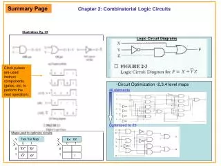
Programmable Logic Arrays (PLA) • Useful for implementing combinatorial functions expressed as sums of products. • AND-OR array having four inputs, twelve product terms and eight outputs.
PLA Implementation of the 7 Segment Display • Implement directly from the original equation. • Note that multiple input lines are shown as one.
PLAs (continued) • Manufactured in standard sizes. • Smallest is 14 inputs, 48 product terms, 8 outputs. • Mask programmed. • EPLD - Can be programmed after manufacture.
Read Only Memories • PLA can be considered as memory. • 14 input PLA can only store 48 words. • 214 = 16384. • In a ROM, all product terms are generated.
Next Lecture Sequential Logic