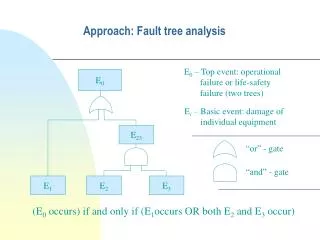
Fault Tree Analysis
Fault Tree Analysis. Part 12 – Redundant Structure and Standby Units. Active Redundancy. The redundancy obtained by replacing the important unit with two or more units operating in parallel. Passive Redundancy.

Fault Tree Analysis
E N D
Presentation Transcript
Fault Tree Analysis Part 12 – Redundant Structure and Standby Units
Active Redundancy The redundancy obtained by replacing the important unit with two or more units operating in parallel.
Passive Redundancy The reserve units can also be kept in standby in such a way that the first of them is activated when the original unit fails, the second is activated when the first reserve unit fails, and so on. If the reserve units carry no load in the waiting period before activation, the redundancy is called passive. In the waiting period, such a unit is said to be in cold standby.
Partly-Loaded Redundancy The standby units carry a weak load.
Life Time of Standby System The mean time to system failure
Exact Distribution of Lifetime If the lifetimes of the n components are independent and exponentially distributed with the same failure rate λ. It can be shown that T is gamma distributed with parameters n and λ. The survivor function is
Approximate Distribution of Lifetime Assume that the lifetimes are independent and identically distributed with mean time to failure μ and standard deviation σ. According to Lindeberg-Levy’s central limit theorem, T will be asymptotically normally distributed with mean nμ and variance nσ^2.
2-Unit System • A standby system with an active unit (unit 1) and a unit in cold standby. The active unit is under surveillance by a switch, which activates the standby unit when the active unit fails. • Let be the failure rate of unit 1 and unit 2 respectively; Let (1-p) be the probability that the switching is successful.
Two Disjoint Ways of Survival • Unit 1 does not fail in (0, t], i.e. • Unit 1 fails in the time interval (τ, τ+dτ], where 0<τ<t. The switch is able to activate unit 2. Unit 2 is activated at time τ and does not fail in the time interval (τ,t].
Probabilities of Two Disjoint Events • Event 1: • Event 2: Unit 1 fails Unit 2 working afterwards Switching successful
Two-Unit System Same as before except unit 2 carries a certain load before it is activated. Let denote the failure rate of unit 2 while in partly-loaded standby.
Two Disjoint Ways of Survival • Unit 1 does not fail in (0, t], i.e. • Unit 1 fails in the time interval (τ, τ+dτ], where 0<τ<t. The switch is able to activate unit 2. Unit 2 does not fail in (0, τ], is activated at time τ and does not fail in the time interval (τ,t].
Probabilities of Two Disjoint Events • Event 1: • Event 2: Unit 1 fails at τ Unit 2 still working after τ Switching successful Unit 2 working in (0, τ]
Possible States of a 2-Unit System with Cold Standby and Perfect Switching
State Space Diagram 4 3 2 0 1
Laplace Transform • Substitute s=0 • Note that
Mean Time to Failure • Take Laplace transform of R(t) • Substitute s=0
Cold Standby, Perfect Switching, With Repairs,A Main Operating Unit
State Space Diagram 4 3 0
State Equations Where
Treating State 0 as An Absorbing State • Take Laplace transform and let s=0 • Solution
Mean Times to Failure and to Repair • Mean time to failure • Mean time to repair
Cold Standby, Imperfect Switching, With Repairs,A Main Operating Unit
State Space Diagram 4 3 0
Partly-Loaded Standby, Perfect Switching, With Repairs,A Main Operating Unit
Possible States of a 2-Unit System with Partly-Loaded Standby and Perfect Switching
State Space Diagram 4 3 0 1
State Space Diagram 0 2 2j 2L 1