Fault Analysis
Fault Analysis. Organization. PART-I Fundamental consideration Why? How? Sequence Components Review. Apparatus Modeling. Fault Analysis Program. PART –II Advanced Topics Purpose of Fault Analysis Reviewed. Role of multipliers for Rotating Machines impedances. E/X and X/R methods.

Fault Analysis
E N D
Presentation Transcript
Organization • PART-I • Fundamental consideration • Why? • How? • Sequence Components Review. • Apparatus Modeling. • Fault Analysis Program. • PART –II • Advanced Topics • Purpose of Fault Analysis Reviewed. • Role of multipliers for Rotating Machines impedances. • E/X and X/R methods. • Example. • PART –III • FAQ’S
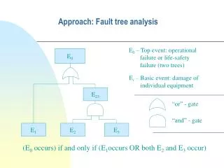
Why? • Electric systems occasionally experience short circuits. • This results in abnormally high currents. • Overcurrent protective devices should isolate faults at a given location safely, with minimal damage. • The parts of system shall be able to withstand the resulting mechanical and thermal stresses. • The magnitudes of fault currents are usually estimated by calculations. • The equipment is selected using the calculation results.
How? • Tedious hand calculation (X) • Fault Analysis program (√ )
Sourcesof Fault Current • Synchronous Generators • Synchronous Motors and Condensers • Induction Machines • Electrical Utility System • Distributed Generation ( modeling in fault analysis. research problem!) • Representation of Rotating Machines. This fault current diminishes as the magnetic field in the machine decays.
What does a fault Analysis program do? • Simulates a fault ( steady state analysis) • SLG • LLG • LL • Three phase • Results • SC – MVA • Fault current (in A) • Contribution of various lines to fault current analysis. (Continued…..)
a a c b b c c a b • Sequence components +ve Seq. Component -ve Sequence 0 Sequence • Unbalanced 3-phase system has six degrees of freedom. • Every balanced set of phasors has two degrees of freedom (Forteskue,1918). • Together +ve,-ve and 0 sequence phasors have six degrees of freedom. • Hence they can be used to synthesize 3phase unbalanced systems.
Unbalanced System and • Sequence Components c1 a1 Positive Seq.component c0 c a1 a2 b1 c2 a0 Zero Seq.components c1 a b0 a0 b c0 b0 Negative Seq.components b2 c2 b2 b1 a2 Unbalanced system
Unbalanced System a a 3a0 b 3a2 c c b a b a c q c 3a1 • Extracting Sequence Components Zero Seq. Components Negative Seq. Components Positive Seq. Components
Advantages of Sequence Transformation • Used when the network is balanced. Provides decoupling in the network. A 3nX3n Linear System Solver is decoupled into three n X n Linear System Solver. • Load may be balanced or unbalanced. • Zero sequence currents provide sensitive earth fault detection technique.
Sequence Components in Fault Analysis Program • Step 1- Three Phase Model . Formulate Admittance Matrix. • Step 2- Sequence Model Formulation. • Step 3- Inject 1.0 p.u. current at bus l i.e. Let, Compute Vl of desired sequencei.e. solve • Zth0,1,2 at l bus= Vl012
Input to Fault Analysis program • Depends on type of fault • Three phase fault. Only Positive Sequence Data. Negative, Zero sequence Network not excited. • SLG fault Positive, Negative, Zero sequence Data. • Typical fault study SLG (√ ) Fault current can range in utility systems from a few percent to possibly 125% of the three phase fault value. Three phase(√ ) In industrial systems line to ground fault current of more than three phase value is rare. LL (X) }fault currents are approximately 87% of three- phase fault current LLG (X)
Role of Per Unit calculation • In the per-unit there are four base quantities: base apparent power in volt-amperes, base voltage, base current and base impedance. • Per – unit quantity = actual quantity/base quantity • The following formulae apply to three- phase system, where the base voltage is the line-to-line voltage in volts or kilovolts and the base apparent power is the three- phase apparent power in kilovolt – amperes or megavolt-amperes.
Advantages of PU Calculations • Manufactures provide equipment data with name plate rating as base. • Range for acceptable % or p.u. values can be easily fixed. • Especially useful in networks with multiple voltage levels interconnected through transformers. • p.u. impedance of transformer is independent of the base. • Standard base conversion (scaling with MVA Base) formulae are available.
Modeling Aspects for Static Apparatus • Transmission Lines, feeder cables etc • Two winding and Three Winding Transformers • Positive sequence Data = Negative sequence Data. • Zero Sequence Data different Rule of Thumb for Lines--- Zero Sequence Data about Three Times Positive Sequence Data. • Zero Sequence Modes of Transformers.
+ ve/- ve sequence connections Zero sequence connections Transformer connections
+ ve/- ve sequence connections Zero sequence connections Transformer connections (d) (e) (f)
Transformer connections + ve/- ve sequence connections Zero sequence connections (g) (h)
Modeling of Rotating Machines Modeling of Synchronous Generator • Xd” = Subtransient reactance; determines the current during the first cycle after fault occurs. In about 0.1 s reactance increases to • Xd’= Transient reactance; assumed to determine current after several cycles at 60Hz. In about 0.5-2 s reactance increases to • Xd=Synchronous reactance; this is the value that determines the current flow after a steady state condition is reached. • Synchronous generator data available from manufacturers includes two values of direct axis reactance – X``dv and X``di. The X``dv value should be used for short – circuit calculations.
Modeling of Synchronous Motors and Condensers • During fault motor acts as a generator to supply fault current • The rotor carrying the field winding is driven by the inertia of the rotor and load. Stator excitation is reduced due to drop in voltage. • The fault current diminishes as the rotor decelerates • The generator equivalent circuit is used for synchronous motor. • The constant driving voltage and three reactance X d”, Xd’ and Xd are used to establish the current values at three points in time. • Synchronous condensers can be treated in same manner as synchronous motors.
Modeling of Induction Machines • During fault rotor is driven by inertia of load and rotor itself. • No dc field excitation on rotor. Rotor winding is short circuited. Hence, whatever rotor excitation is present, it is due to the induced fields in the rotor from the rotating stator mmf. As stator excitation is lost and rotor slows down this field is lost quickly. • The current contribution of an induction motor to a terminal fault reduces and disappears completely after a few cycles. As a consequence only the sub transient value of reactance X``d is assigned. This value is about equal to the locked – rotor reactance. • For fault calculations an induction generator can be treated as an Induction motor. • Wound rotor induction motors normally operating with their rotor rings short – circuited will contribute fault current in the same manner as a squirrel cage induction motor. • Occasionally large wound – rotor motors operated with some external resistance maintained in their rotor circuits may have sufficiently low short circuit time constants that their fault contribution is not significant and may be neglected.
Negative Sequence Impedance for Synchronous Machines • Positive and negative sequence impedances cannot be equal. • In case of synchronous machine, -ve sequence currents creates a rotating mmf in opposite direction to the rotor mmf. Double frequency emf and currents induced in rotor. • -ve sequence impedance is 70-95 % of subtransient reactance. It can be approximated by subtransient reactance. For a salient pole machine it is taken as a mean of Xd” and Xq”.
Zero Sequence Impedance of Synchronous Machine • Zero Sequence Currents cannot create rotating mmf (why ?) • Hence, Zero Sequence Impedance is only a small % (0.1-0.7) of the +ve sequence impedances. • It varies so critically with armature winding pitch that an average value can hardly be given. • Since synchronous machines only generate +ve sequence voltage, the internal voltages used with negative sequence and zero sequence networks is zero. • If Y point is grounded through an impedance Zg, then 3Zg will have to be added to zero sequence impedance of generator before incorporating in YBUS.
Sequence Modeling of Asynchronous Machines (IM) • Transient state of the current damped quickly (1-2 cycles) • Subsequently machine behaves as a passive element with impedance of value Z=kVll^2/Smva where rated LL voltage and 3phase MVA rating is used. • Zero Sequence modeling can be treated in similar lines to as synchronous machines because rotor plays no significant role.
Modeling of Electric Utility Systems • The generator equivalent circuit can be used to represent the utility system • The utility generators are usually remote from the industrial plant. • The current contributed to a fault in the remote plant appears to be merely a small increase in load current to the very large central station generators, and this current contribution tends to remain constant. • Usually represented at the plant by a single – valued equivalent impedance referred to the point of connection.
Modeling of Mutually Coupled Lines Circuit 2 Circuit 1 c1 a1 a2 c2 b1 b2 • If the lines a1, b1 and c1 carry balanced +ve or –ve sequence currents, flux linking circuit 2 is zero (as per Ampere’s law). • For zero sequence currents in circuit 1, flux linking circuit 2 is not zero. • Hence, mutual coupling is only considered in zero sequence networks. • Procedure is given in the book.
Effect of Mutual Coupling on Sequence Network representation Let two X mission lines emanating from the same tower (double circuit) be coupled with each other. If both lines are transposed ,then average mutual coupling between any two phases of the 2-lines will be identical.
Mutual Coupling contd… After sequence transformation. MUTUAL COUPLING IS SEEN ONLY IN ZERO SEQUENCE NETWORK
Conclusions 1. 3 Fault currents, LL fault currents will not be affected by Mutual Coupling. 2. For all faults involving ground (SLb,LLb), If will be affected by mutual coupling. 3. It will affect performance of relays & relay coordination should account for it.