Download
1 / 31
310 likes | 408 Vues
This project focuses on designing a Front End Detector Card with low power consumption and high performance for a 128-channel digital circuit system. The card features TPC electronics with specialized components such as ADC, memory, and digital processors. The architecture includes custom integrated circuits (CMOS), specific signal processing methods, and efficient data compression techniques. The design incorporates innovative technologies like digital tail cancellation and adaptive baseline correction to enhance signal processing and data integrity. The system is intricately built to meet strict power requirements while delivering optimal performance in detecting and processing signals in a drift region. The project encompasses the development and testing of various prototypes, including the RCU and FEE boards, to ensure the system's functionality and compatibility with different components. The focus lies on achieving high precision, rapid data processing, and reliable data transmission in a compact electronic setup.

E N D
Digital Circuit TPC FEE FEC (Front End Card) - 128 CHANNELS (CLOSE TO THE READOUT PLANE) DETECTOR Power consumption: < 40 mW / channel L1: 5ms 200 Hz 8 CHIPS x 16 CH / CHIP 8 CHIPS x 16 CH / CHIP drift region 88ms L2: < 100 ms 200 Hz gating grid PASA ADC RAM anode wire DDL (4096 CH / DDL) 570132 PADS CUSTOM IC (CMOS 0.35mm) pad plane CUSTOM IC (CMOS 0.25mm ) CSA SEMI-GAUSS. SHAPER 1 MIP = 4.8 fC S/N = 30 : 1 DYNAMIC = 30 MIP • BASELINE CORR. • TAIL CANCELL. • ZERO SUPPR. 10 BIT < 10 MHz MULTI-EVENT MEMORY GAIN = 12 mV / fC FWHM = 190 ns
DIGITAL PROCESSOR & CONTROL LOGIC 8 ADCs 8 ADCs MEMORY TPC electronics:ALICE TPCE READOUT CHIP (ALTRO) ADC Adaptive Baseline Correct. I Tail Cancel. Adaptive Baseline Correct. II Data Format. Multi-Event Memory + - 10- bit 20 MSPS 11- bit CA2 arithmetic 18- bit CA2 arithmetic 11- bit arithmetic 40-bit format 40-bit format SAMPLING CLOCK 20 MHz READOUT CLOCK 40 MHz 0.25 mm (ST) area:64mm2 power:29 mW / ch SEU protection DIGITAL TAIL CANCELLATION PERFORMANCE ADC counts ADC counts Time samples (170 ns)
Data compression: Entropy coder Probability distribution of 8-bit TPC data Results: NA49: compressed event size = 72% ALICE: = 65% (Arne Wiebalck, diploma thesis, Heidelberg) Variable Length Coding short codes for long codes for frequent values infrequent values
RCU design – control flow TTCrx SIU controller FEE bus controller DDL command decoder • State machines FEE SC RCU resource & priority manager Huffman encoder Slow control Watch dog: health agent Debugger PCI core
RCU design - data flow • Shared memory modules TTC controller TTCrx registers FEE bus controller Event memory SIU controller fifo FEE bus controller Event fragment pointer list SIU Huffman encoder FEE bus controller Configuration memory Slow control
Data compression: TPC - RCU • Pipelined Huffman Encoding Unit, implemented in a Xilinx Virtex 50 chip* • TPC front-end electronics system architecture and readout controller unit. * T. Jahnke, S. Schoessel and K. Sulimma, EDA group, Department of Computer Science, University of Frankfurt
RCU prototypes • Prototype I • Commercial OEM-PCI board • FEE-board test (ALTRO + FEE bus) • SIU integration • Qtr 3, 2001 – Qtr 2, 2002 • Prototype II • Custom design • All functional blocks • PCB: Qtr 2, 2002 • Implementation of basic functionality (FEE-board -> SIU): Qtr 2, 2002 • Implementation of essential functionalty: Qtr 4, 2002 • Prototype III • SRAM FPGA -> masked version or Antifuse FPGA (if needed) • RCU production • Qtr 2, 2003
RCU prototype I • Commercial OEM-PCI board • ALTERA FPGA APEX EP20K400 • SRAM 4 x 32k x 16bits • PMC I/O connectors (178 pins) • Buffered I/O (72 pins)
RCU prototype I FEE boards trigger • Implementation of basic test functionality • FEE-board test (ALTRO + FEE bus) • SIU integration FEE-bus daughter board PMC PCI bus FPGA APEX20k400 PCI core I/O SIU card internal SRAM 4 x 32k x 16 FLASH EEPROM onboard SRAM
RCU prototype II • Implementation of essential functionality • Custom design • All functional blocks SC TTC FEE-bus PCI bus SIU-CMC interface PCI core FPGA SIU internal SRAM > 2 MB FLASH EEPROM Memory D32
SRAM SRAM SRAM SRAM SRAM SRAM SRAM SRAM SDRAM RCU prototype II - schematics CIA miscellaneous JN2A JN1 JN2 Flash Power (1.8V Gen.) Flash Flash JN3 JN4 JN5 APEX Connectors
Front-End Bus Conn 1 RCU Mezzanine Card Components on top side No maximum height restriction Front-End Bus Conn 2 RCU prototype II – RCU mezzanine
Front-End Bus Conn 1 RCU Mezzanine Card Components on top side No maximum height restriction SRAM SRAM SRAM SRAM SRAM SRAM SRAM SRAM Front-End Bus Conn 2 SDRAM RCU prototype II - schematics SIU / DIU mezzanine card (1/2 CMC) CIA miscellaneous JN2A JN1 JN2 Flash Power (1.8V Gen.) Flash Flash JN3 JN4 JN5 APEX Connectors
Programming model PCI-tools PC LINUX RH7.1 (2.4.2) RCU-API • Development version – status December 2001 device driver PCI core mailbox memory PLDA board FEE bus controller SIU controller ALTRO emulator FEE bus SIU ALTRO emulator DDL
SIU-RORC integration RCU prototype I LINUX/NT PLDA/PCI-tools RCU-API devicer driver SIU FPGA interface SIU controller PCI core SIU SRAM PCI bus DDL pRORC LINUX DDL/PCI-tools pRORC-API device driver DIU Glue logic PCI bridge interface DIU PCI bus
SIU-RORC integration PC1: write memory block to FPGA internal SRAM PC1 memory block • Result data control PC2: allocate bigphys area, init link + pRORC SIU controller: wait for READY-TO-RECEIVE RCU internal SRAM PC2: send DDL-FEE command READY-TO-RECEIVE SIU SIU controller: strobe data into SIU DDL pRORC: copy data into bigphys area via DMA DIU PC2 ”bigphys” memory area =
RCU system for TPC test 2002 Trigger FEE-boards FEE-bus LINUX RH7.x DATE PLDA/PCI-tools RCU-API devicer driver SIU FPGA interface RCU prototype II/I FEE-bus controller SIU controller Manager PCI core SIU SRAM FLASH ext. SRAM PCI bus DDL LINUX RH7.x DATE DDL/PCI-tools pRORC-API device driver DIU Glue logic PCI bridge interface DIU pRORC PCI bus
Programming model DATE FEE configurator PC LINUX RH7.1 (2.4.2) PCI-tools RCU-API • TPC test version – summer 2002 device driver PCI core mailbox memory Prototype II (Prototype I) RCU resource & priority manager SIU controller FEE bus controller FEE bus SIU FEE boards DDL
FLASH EEPROM TPC PCI-RORC PCI bus FPGA Memory DIU - CMC PCI bridge Glue logic Coprocessor D32 interface ³ internal 2 MB DIU card SRAM 2 MB Memory D32
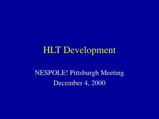
RcvBd RcvBd RcvBd RcvBd NIC NIC NIC NIC NIC NIC NIC NIC NIC NIC HLT architectureoverview Optical Links to Front - End • Not a specialized computer, buta generic large scale (>500 node) multi processor cluster • A few nodes have additional hardware (PCI RORC) • has to be operational in off-line mode also • Use of commodity processors • Use of commodity networks • Reliability and fault tolerance is mandatory • Use standard OS (Linux) • Use of on-line disks as mass storage Receiver Processos / HLT Processor RcvBd RcvBd RcvBd RcvBd RcvBd RcvBd RcvBd RcvBd PCI PCI PCI PCI PCI PCI PCI PCI NIC NIC NIC NIC NIC NIC NIC NIC Distributed Farm Controller HLT Network PCI PCI NIC NIC PCI NIC NIC Monitoring Server PCI PCI PCI PCI PCI PCI PCI PCI PCI PCI NIC NIC NIC NIC NIC NIC NIC NIC NIC NIC HLT Processors
HLT - Cluster Slow Control • Features: • Battery Backed Completely independent of host • Power Controller Remote powering of host • Reset Controller Remote physical RESET • PCI Bus perform PCI bus scans, identify devices • Floppy/flash emulator create remotely defined boot image • Keyboard driver remote keyboard emulation • Mouse driver remote mouse emulation • VGA replace graphics card • price very low cost • Functionality: • complete remote control of PC like terminal server but already at BIOS level • intercept port 80 messages (even remotely diagnose dead computer) • interoperate with remote server, providing status/error information • watch dog functionality • identify host and receive boot image for host • RESET/Power maintenance
HLT Networking (TPC only) All data rates in kB/sec (readout not included here) 92 000 spare 7 000 65 000 92 000 spare 180 links, 200 Hz 92 000 spare 65 000 7 000 92 000 17 000 000 2 340 000 252 000 ? aggregate cluster finder 180+36 nodes Track segments 108+36 nodes Track merger 72+36 nodes Global L3 12 nodes Assume 40 Hz coinzidence trigger plus 160 Hz TRD pretrig with 4 sectors per trigger
HLT Interfaces • HLT is autonomous system with high reliabilitystandards (part of data path) • HLT has a number of operating modes • on-line trigger • off-line processor farm • possibly combination of both • very high input data rates (20 GB/sec) • high internal networking requirements • HLT front-end is first processing layer • Goal: same interface for data input, internal data exchange and data output HLT internal, input and output interface Publish/subscribe: • When local do not move data – Exchange pointers only • Separate processes, multiple subscribers for one publisher • Network API and architecture independent • Fault tolerant (can loose node) • Consider monitoring • Standard within HLT and for input and output • Demonstrated to work on both shared memory paradigm and sockets • Very light weight
HLT system structure TRD trigger PHOS trigger Dimuon trigger Trigger detectors Level-1 Pattern Recognition TPC: fast cluster finder + fast tracker Hough transform + cluster evaluator Kalman fitter Dimuon arm tracking Level-3 Extrapolate to ITS ... Extrapolate to TOF Extrapolate to TRD (Sub)-event Reconstruction
Preprocessing per sector raw data, 10bit dynamic range, zero suppressed Huffman encoding (and vector quantization) RCU detector front-end electronics Huffman decoding, unpacking, 10-to-8 bit conversion fast cluster finder: simple unfolding, flagging of overlapping clusters RORC fast track finder initialization (e.g. Hough transform) cluster list fast vertex finder Hough histograms Peakfinder receiver node global node vertex position raw data
FPGA coprocessor: cluster finder • Fast cluster finder • up to 32 padrows per RORC • up to 141 pads/row and up to 512 timebins/pad • internal RAM: 2x512x8bit • timing (in clock cycles, e.g. 5 nsec)1: #(cluster-timebins per pad) / 2 + #clusters • outer padrow: 150 nsec/pad, 21 sec/row • centroid calculation: pipelined array multiplier 1. Timing estimates by K. Sulimma, EDA group, Department of Computer Science, University of Frankfurt
FPGA coprocessor:Hough transformation • Fast track finder: Hough transformations2 • (row,pad,time)-to-(2/R,,) transformation • (n-pixel)-to-(circle-parameter) transformation • feature extraction: local peak finding in parameter space 2. E.g. see Pattern Recognition Algorithms on FPGAs and CPUs for the ATLAS LVL2 Trigger, C. Hinkelbein et at., IEEE Trans. Nucl. Sci. 47 (2000) 362.
Processing per sector raw data, 8bit dynamic range, decoded and unpacked vertex position, cluster list slicing of padrow-pad-time space into sheets of pseudo-rapidity, subdiving each sheet into overlapping patches RORC sub-volumes in r,, fast track finder B: 1. Hough transformation fast track finder A: track follower fast track finder B: 2. Hough maxima finder, 3. tracklett verification track segments receiver node cluster deconvolution and fitting updated vertex position updated cluster list, track segment list