A/C SYSTEM COMPONENTS
A/C SYSTEM COMPONENTS. A/C System Components. Evaporator Condenser Compressor Expansion valve TXV Filter dryer Refrigerant hoses Control devices. A/C System. Condenser. Compressor. Evaporator. Filter dryer. Expansion valve. Evaporator core. Evaporator core with plaques.

A/C SYSTEM COMPONENTS
E N D
Presentation Transcript
A/C System Components • Evaporator • Condenser • Compressor • Expansion valve TXV • Filter dryer • Refrigerant hoses • Control devices
A/C System Condenser Compressor Evaporator Filter dryer Expansion valve
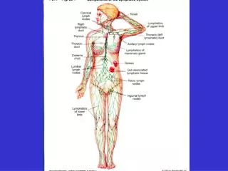
Air Conditioner Group AE - External air inlet AI - Recirculating air SPA - Recycle flap E - Evaporator core SM - Heater flap R - Heater core DA - Windscreen air flow BF - Front air flow DP - Floor air flow SDI / SDS - Air distribution flap
Condenser(parallel flow) Gaseous refrigerant inlet 1 - Fan 2 - Condenser Liquid refrigerant outlet
Condenser(refrigerant flow) Gas Liquid
A/C Compressors • Piston • Fixed and Variable stroke • Rotary vanes • Fixed stroke SD7B10 (Fixed) SD7H15 (Fixed) SP 10 (Fixed) V 5 (Variable) CVC (Variable) SS 10 SS121DS
SS 10 Compressor(Rotary vanes) 1 - Suction port 2 - Discharge port 3 - Thermoswitch 4 - Oil separator 5 - Casing 6 - Vane 7 - Rotor 8 - Stator 9 - Discharge valves
Harrison SP10(5 double effect pistons) 1 - twin-effect piston 2 - yoke 3 - swash disk 4 - back cylinder block 5 - shaft 6 - back housing 7 - front housing 8 - fron cylinder block
Harrison V5 Compressor(Five piston, variable stroke) 1 - Swash plate 2 - Rod 3 - Piston 4 - Regulation valve 5 - Shaft
V5 - Stoke regulation valve 1 - Valve casing 2 - Boost control capsule 3 - Regulation pin 4 - Sphere 5 - Return spring A - HP manifold B - Crankcase inlet C - Crankcase discharge D - LP manifold X - Crankcase to LP flow Y - HP to crankcase flow
V5 - Regulation Stroke increasing Stroke decreasing
Electro-magnetic clutch 1 - through bolt 2 - washer 3 - driving plate 4 - pulley assembly 5 - pulley 6 - dust shield 7 - bearing 8,9 - snap rings Seeger 10 - mounting bolt 11 - magnetic coil
Piston Discharge chamber Variable orifice Crankcase Swash plate Suction chamber Swash Plate Externally Controlled Clutchless Compressor Min Displacement Max Displacement Discharge chamber Control valve (Open) Control valve (close) Suction chamber
TXV expansion valve - H type To Compressor’s Suction port From Filter dryer
Filter dryer 1 - Casing 2 - Fittings block 3 - Inlet 4 - Outlet 5 - Pressure switch port 6 - Sight glass (*) 7 - Outlet pipe 8 - Higroscopic material 9 - Micro filter 10 - Holed screen
Refrigerant hoses R134a 1 - Elastomer 2 - Textile plait renforcement 3 - Nylon barrier R12 1 - Elastomer 2 - Textile plait renforcement
Fittings(examples) Male O-Ring 90° Male flanged 45° for expansion valve connection Male flanged 90° for expansion valve connection ROTALOCK 90° for compressor
Refrigerant hoses(connection) 13/32” 1/2” 5/16” 5/16”
Control devices • Pressure switch (trinary) • HP side protection • Condensation pressure regulation Controlled component: • Compressor • Condenser’s fan • Thermostatic switch • Evaporator’s temperature regulation Controlled component: • Compressor
1 2 3 4 5 6 Four levels Pressure switch Pmin Pmax 1° Step Fan 2° Step Fan working pressure values (A.P.) I. & II. livel Compressor ON: > 2,5 bar (min); < 28 bar (max) III. Livel Fan 1° Step : ON > 15 bar; OFF < 12 bar IV. livel Fan 2° Step : ON > 20 bar; OFF < 15 bar
Wiring diagram(example) 1 - Pressure switch 2 - Compressor 3 - Thermostatic switch 4 - Relays 5 - Power source (+ 12V) 6 - Condenser’s fan 7 - Command signal from A/C switch
Refrigerant hoses Lay-out TXV port evaporator quadrinary and H.P. ports 1/2” 5/16” (D.6) 5/16” Pressure dumper Compressor port Receiver dryer port 13/32” condenserport 5/16”