Inspection and Testing
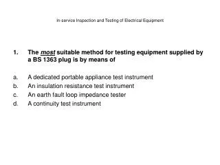
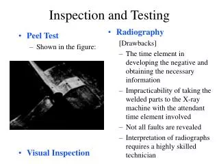
Radiography [Drawbacks] The time element in developing the negative and obtaining the necessary information Impracticability of taking the welded parts to the X-ray machine with the attendant time element involved Not all faults are revealed

Inspection and Testing
E N D
Presentation Transcript
Radiography [Drawbacks] The time element in developing the negative and obtaining the necessary information Impracticability of taking the welded parts to the X-ray machine with the attendant time element involved Not all faults are revealed Interpretation of radiographs requires a highly skilled technician Peel Test Shown in the figure: Visual Inspection Inspection and Testing
Button Size as a Measure of Weld Quality Button Diameter
Modes of Failure in Spot Welds Full Button Irregular Button Interfacial Failure
Long Life Test -- on 1.3-mm Thick 6009-T4 Arc Cleaned/Conversion-Coated Sheet with Truncated Cone Electrodes and Current Stepping Percent Heat (%) Button Diameter (mm) [Reference: SAE 840291, Patrick, Auhl, and Sun] Undersized Buttons/Strip Number of Welds
Shear-Strength Data for Long Life Test -- on 6009-T4 Arc Cleaned/Conversion-Coated Sheet Shear Strength (kN/Spot) [Reference: SAE 840291, Patrick, Auhl, and Sun] Number of Welds
Minimum Tensile-Shear Strength of Spot Welds in Aluminum Alloys [Reference: Resistance Welding Manual, p.11-26, RWMA]
Resistance Spot Weld Radiographs 1 mm Sheet 6009/6009 5182/5182 2036/2036 Large Cracking Small Cracking Large Center Porosity [Reference: Joining of Aluminum Alloys 6009/6010, Hoch]
Undersize nugget Inadequate diameter Inadequate penetration Oversize nugget Excessive diameter Excessive penetration Odd and misshapen nuggets Extent of Alclad inclusion into the nugget Extrusion of the nugget Cracking of the nugget Porosity Expulsion from faying surfaces Segregation of eutectic in parent material Electrode pickup Size or extent or granular zone Nugget penetration Types of Defects Revealed by Radiography
[Step 1] Insert electrode of proper size and tip contour for the gauge combination. Align electrodes. [Step 2] Set pressure gage for suggested welding force, and check with an electrode force gauge. [Step 3] Adjust the control to provide the approximate suggested weld and “postheat time”. [Step 4] The welding currents shown are approximate and intended to be a guide. The magnitude of the welding current is usually controlled by a heat dial or phase-shift control. [Step 5] Check the machine for consistency of operation by making and testing twenty single spot tension-shear specimens and five macroscopic examination specimens. Setup Procedures and Suggested Schedules
Typical Oscillograph Record during Welding Voltage 1 V Force Forge Force 1 kN Welding Force 0.25 mm Displacement Current 5.0 kA rms 0.1 sec
Typical Oscillograph Record 5.2 kA RMS Current 0.7 kN Force 0.2 mm Zero line for force Displacement 1.0 V (p-t-p) Voltage
Resistance Spot Weld Data [Reference: Guidelines to Resistance Spot Welding Aluminum Automotive Sheet, p.9, The Aluminum Association]
Shunting Effect on 2024-T Alclad Factors Influencing Shunting Effect Include: • Thickness and resistance of the alloy being welded • Shunting effect increases as the stock thickness and resistance decrease • Surface resistance of the faying surface • Shunting effect increases as the faying surface resistance increases • Spot spacing • Shown in left figure Shunt Path Resistance, Microohms Joint Strength, lb/weld Joint Strength Shunt Resistance Weld Spacing, in. [Reference: Resistance Welding Manual, p.11-19, RWMA]
Suggested Minimum Weld Spacing Edge and Flange Distance [Reference: Resistance Welding Manual, p.11-20, RWMA]