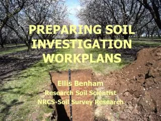
EXECUTION OF SOIL INVESTIGATION AND FOUNDATION
POWER GRID CORPORATION OF INDIA LIMITED. HYDERABAD SS. EXECUTION OF SOIL INVESTIGATION AND FOUNDATION. by M.KRISHNA MURTHY Sr.Engineer (TLM) Hyderabad SS. Soil Investigation.

EXECUTION OF SOIL INVESTIGATION AND FOUNDATION
E N D
Presentation Transcript
POWER GRID CORPORATION OF INDIA LIMITED HYDERABAD SS EXECUTION OF SOIL INVESTIGATION AND FOUNDATION by M.KRISHNA MURTHY Sr.Engineer (TLM) Hyderabad SS
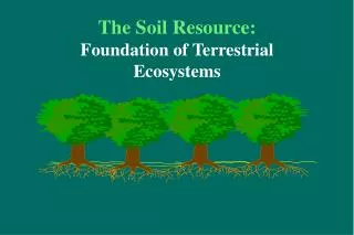
Soil Investigation • Soil investigation is necessary for selection of safe foundation design along the entire Transmission Line Route. • Foundations are designed to transfer all types of loads coming from structure to the soil safely • Foundations are designed to satisfy the following criteria: • 1 Location and depth criteria • 2 Stability criteria or bearing capacity criteria • Settlement criteria • After finalizations of the route alignment, specific locations are identified for carrying out Soil Investigation to classify the foundations w.r.t above criteria
Soil Investigation • The purpose of Soil Investigation is to obtain sufficient information about sub-strata profile of the soil for proper foundation classification in particular area of the Transmission Line route. • It gives us general idea of the soil properties likely to be encountered along the line route.
Soil Investigation • Standard Penetration Test(SPT) • Normal soil- 2, 3, 5, 7 mts • River crossing and special towers- 2, 3, 5, 7 and thereafter at an internal of 3 mts
Soil Investigation • Standard Penetration Test (SPT) • This test is carried out by driving a split spoon sampler in bore hole by means of 650N hammer having free fall of 0.75 mts. The sample shall be driven by using hammer for 450mm and recording the counts. The number of blows for last 300mm drive shall be reported as N value.
Soil Investigation • Disturbed sampling is done for every half meter • UD for 1, 4 and 7 mts.
Soil Investigation • Following types of soil investigation methods are adopted in POWERGRID. • 1 By visual inspection of the area and collection of information from locals. • 2 By way of Trial Pit or Bore Log, depending upon the contract conditions. • 3 SPT method up to 10 metes. of depth. • 4 SPT method up to 40 metes. depth for river crossing locations.
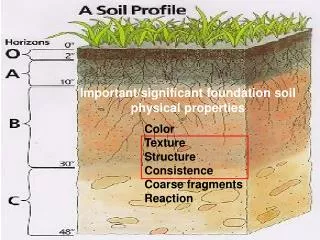
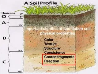
Soil Investigation • Classification by visual inspection. • This is most important method and requires lot of experience for a person responsible to take decision on Foundation Classification at site. • This method is used for most of the locations. • The information about water table and crop pattern is gathered from locals which helps in deciding the foundation classification
Soil Investigation • Bore log/ Trial pit method: • Bore log/trial pit method is adopted for all the tower locations. In this case foundations are classified by visual inspection of the soil samples collected at various depths and co-relating the same with the prevailing site conditions. • The data collected by visual inspection is put in use with bore log\trial pit data to arrive at any decision • In our contracting system, Bore Log is a paid item but Trial Pit is un-paid item.
Soil Investigation • SPT up to 10 meters depth: • This is scientific method of examination of soil so as to arrive at a decision of safe foundation. • It is generally done every four kilometers. Preference is given to the angle towers. All special towers/rail crossing towers are to investigated irrespective of distance criterion. • In this case 150mm diameter bore is drilled up to 10 meters and un disturbed samples and N value (by SPT method) is recorded at 2 3 5 7 & 10 meters depth. Disturbed samples are collected every 0.5 meters or change of strata, which ever is earlier.
Soil Investigation • SPT up to 10 meters depth: • It is the responsibility of site In-charge to ensure collection of the samples at site and record correct N Value. • The soil samples are sealed and sent to laboratory for detailed testing. • Sub soil water table is recorded after 24 hours.
Soil Investigation • As Soil Investigation is not done on all the locations, most of the foundation locations are required to be recommended on the basis of visual inspection of the area. • For effective decision at site, required to be taken by site engineers, POWERGRID deals in detail in the Technical Specifications of every contract, the Parameters to be considered while recommending the foundations Foundation Classification of a particular location.
Soil Investigation • Required field & laboratory tests are • conducted to arrive at requisite soil • parameters and strength to facilitate in • optimum foundation design. • Chemical tests on sub-soil water and soil • samples • Highest flood level (H.F.L.), Maximum river • velocity and Maximum river discharge data • are collected.
Soil Investigation • Field Tests • Inspection of various soil samples collected during the course of drilling • Recording of N value of Standard Penetration Test • Recording of depth of Ground Water Table and collection of water samples for lab testing.
Soil Investigation • Laboratory tests • Liquid limit and plastic limit • Natural moisture content • Grain Size Analysis (Sieve analysis) • Tri-axial test • Direct shear test • Specific Gravity. • Calculation of safe bearing capacity of soil
Soil Investigation • For River Crossing locations (SPT up to 40 meters): • Minimum borehole diameter 150mm • SPT Carried out at 2.0m, 3.0m, 5.0m, 7.0m, 10.0m and thereafter at the rate of 3.0m intervals to 40.0m depth and at 40.0m. • Undisturbed soil sample collected at 1.0m, 4.0m, 6.0m, 8.0m, 11.0m and thereafter at the rate of 3m intervals. • Disturbed soil sample collected at 0.5m interval starting from 0.5m below GL
Soil Investigation SHELL & AUGER UNIT CAN DRILL UPTO 40 M DEPTH THROUGH SOILS & MIXED WITH PEBBLES, GRAVELS, CHISELLING CAN BE DONE
TL Construction FOUNDATION
General Design Criteria • Design of safe & economical foundation is based on soil properties, knowledge of soil structure & settlement analysis • Loads on Tower Foundation:- • - Downward load • - Uplift load • - Lateral Load (Horizontal thrust) • - Overturning moments
General Design Criteria • Downward load- Mainly due to deadweight of • tower & conductor • Uplift load - Primary concern in design • - Due angle of deviation, difference in level, dead ending • Lateral Load - Due to wind • Wind produces both lateral as well • as uplift on the windward side of • structure and down thrust on the • other side • Factor of Safety - 2.2 for normal condition • - 1.65 for broken wire condition
What to do before casting of Tower Foundation • Finalize Route of Transmission line • Carry out Detailed Survey • Carry out Soil Investigation • Finalize Tower Schedule (Part/Full) • Carry out Check Survey
Locating the foundation location 1. Locate the exact location by Check Survey. 2. Taking the back reference fix the alignment in line with the route finalised during the Detailed Survey. 3. Once the direction is fixed mark the intermediate suspension tower’s center point peg. 4. Distance between the point of reference center point to the center point of the tower under reference should be exact distance as marked in the tower schedule.
Locating the foundation location(Contd.) 5. Same process should be followed for all the intermediate towers till the next Angle Point. 6. Compare the physical situation of each tower location with the Elevation and Plan Section as detailed in the profile. 7. For each Location fix three pegs to give the line direction.
Marking Intermediate Towers TOTAL STATION Q AP1 30o AP2 A 3 A 2 A 1 380m P 1. First center total station on center peg of the Angle Point 2. View the back reference / line direction peg ‘P’ by the Theodolite / Total Station. 3. Transit the telescope to the line direction peg ‘Q’. 4. Rotate telescope 30oL with reference to direction peg ‘Q’. 5. Mark the intermediate towers A1, A2, A3 ……
Classification of Foundation 1. It is the most difficult task since the Transmission Line passes through different terrains and come across different soil strata and remoteness of the construction. 2. Various methods were adopted by different Organisations to classify the foundation. Generally the cost of foundation is 8% to 14% of the cost of Transmission Line. 3. Before we proceed further for classification of Foundations, we should know, what are types of forces acting on the foundation.
Foundation resists the following types of forces: a) Uplift / the Tension. b) Downward Thrust / the Compression. c) Lateral Load. d) Over Turning Moment. The magnitudes of limit loads on foundation should be taken 10% higher than those adopted for the corresponding tower. 4. How forces act?
Forces Acting on a Tower Total wind force on tower = F Wind moment on foundation = T&L Wind Shear = F Compression on Foundation ( C =T ) Uplift on Foundation (T) L Shear Force Shear Force
5. Soil parameters required to take care of the load as indicated above are as follows: a) Limit bearing capacity of soil. b) Density of soil. c) Angle of Earth frustum. 6. For designing foundation the soil properties are generally obtained by the method as follows: a) By conducting soil investigation. b) From available data bank of soil strata of different states. 7. Limit Bearing Capacity: This parameter is vital to establish the stability of foundation against shear failure of soil and excessive / uneven settlement.
8. Density of soil: This parameter is required to calculate the uplift resistance of foundation. 9. Angle of Earth Frustum: This parameter is required for finding out the uplift resistance. SOIL INVESTIGATION: To determine the above check, various procedure are followed in the Transmission Line to find out the properties of the soil which are as follows: 1. To carry out the soil investigation throughout the Line at an interval of 350 to 400 m.
2. Present practice in POWERGRID is to carry out soil investigation at all the major Power Line crossing, Railway crossing, National Highway crossing, at an interval of 15 locations along the Route, at Angle Towers, where the soil strata changes and at Special Locations . 3. During execution stage trial pits upto a minimum depth of 3.0m shall be excavated at each and every location in order to classify the type of foundation after obtaining following details. (i) Type of soil encountered. (ii) Ground water table.
Classification and Properties of soil: 1. Where the soil investigations are carried out, the soil properties are determined and based on which classification can be done. 2. Where only trial pits or visual observation is done, then Engineer’s needs to apply the knowledge by their understanding of soil properties.
Types of Soil: a) Non-cohesive soil: 1. Gravel, compact sand, gravel mixture and offering high resistance to penetration during excavation. 2. Coarse sand, compact and dry 3. Medium sand, compact and dry 4. Fine sand, Silt (dry lumps easily pulverized by the fingers) 5. Loose gravel or sand, gravel mixture loose coarse to medium sand, dry.
b) Cohesive soils: 1. Soft shale hard or stiff in deep bed, dry. 2. Medium clay, readily indented with thumb nail. 3. Moist clay and sand clay mixture. 4. Soft clay and very soft clay. 5. Black cotton soil or other shrinking/expansive clay. For further understanding of classification, the cohesive soil gets unified with the parent soil after back filling with the passage of time.
The following soils comes under this category: a) Normal soil having mixture of silt and clay (clay not exceeding 15%). This type of soil in wet condition can be rolled between the palms, only short threads can be made. b) Clayee soils having high percentage of clay (more than 15% ) e.g., Black cotton soil (can be black or yellow). This type of soil in wet condition can be rolled within the palms a long thread can be made. c) Marshy soil having sea mud (Marine soil) which are very sticky In nature.
Types of rocks: a) Soft rock / Fissured rock: Include decomposed or fissured rock, hard gravel, kankar, lime stone, laterite or any other soil having similar nature. These types of rocks can be excavated using normal tools. b) Hard rock: Include hard sand stone, quartzite, granite, basalt, hard marble etc. These types of rocks can be excavated through blasting, chiseling and drilling.
Classification of Foundation: a) Classification of foundation mainly through visual observation and trial pits, depends on the factors as follows: 1. Type of Soil. 2. Water Table. b) Based on this key factor the normal standardized design of foundation are as follows. TYPECONSIDERATION 1. Normal dry Foundation: i) Soil cohesive and homogeneous up to full depth. ii) Clay content (10% to 15%) iii) Water below foundation level.
TYPECONSIDERATION 2. Wet Foundation. i) Soil condition as above. ii) Sub soil water at depth 1.5m or more below GL. iii) Standing water with penetration not exceeding 1m (Paddy field). 3. Partly Submerged. i) Soil condition as above. ii) Sub-soil water at depth between 1.5m & 0.75m below GL. 4. Fully Submerged. i) Soil condition as above. ii) Sub-soil water at a depth within 0.75m below GL.
TYPECONSIDERATION 5. Black cotton Foundation i) Soil cohesive, clay exceeding 15% having characteristic of high shrinkage and swelling (Black & Yellow). ii) Soil of same nature exceeds 50% and extends upto full depth. iii) Where top layer is normal / good soil up to 50% of the depth but below is WBC. 6. Soft Rock or Fissured i) Soil non-cohesive, decomposed or fissured rock, hard gravel, hard morrum, laterite or similar nature can be cut normal tools. (WBC) rock Foundation
TYPECONSIDERATION 7. Submerged Fissured i) Soil is same as Fissured Rock. ii) Sub-soil water within 0.75m or below 0.75m from GL. 8. Hard rock foundation i) Where hard rock is encountered at 1.5m or less below GL. 9. Partial black cotton i) Where top layer of black cotton soil exceed upto 50% of depth and there after good soil. 10. Hard rock foundation i) Where hard rock is from 1.5m to 2.5m below GL (top layer is good soil). rock foundation with chimney for normal soil
TYPECONSIDERATION 11. Hard rock foundation i) Where hard rock is 1.5m to 2.5m below GL (top layer is BC or fissured rock). 12. Normal dry with i) Where top layer upto 1.5m below GL is normal dry soil and thereafter hard soil / murrum. 13. Dry sandy soil i) Sandy soil with clay content not exceeding 10%. 14. Wet sandy soil i) Sandy soil with Water Table in pits. with chimney for WBC undercut foundation foundation Any other combination of soil not covered above shall require development of special foundation design after detailed soil investigation.
The above categorization of foundation is mainly done because of: 1. Standardization of foundation to take care of normal variation of soil. 2. To implement speedy execution by quick decisions. 3. Simplifying the process of erection requiring less expenditure in execution.
Based on the above criteria of loading and soil parameters various types of foundations are designed for adoption in Line are generally as follows: A) Chimney and Pyramid Type: ELEVATION ELEVATION PLAN A-A PLAN A-A These foundations need form boxes. Commonly used in cohesive soils. Stepped foundations need less shuttering but adequate care should be taken for monolithic jointing of concrete in intermediate steps.