Download
1 / 25
250 likes | 388 Vues
Outline HYSPEC: project timeline and place in the SNS instrument suite HYbrid SPECtrometer’s layout and principal features Polarized beam setup: principle and components Performance optimization of the (Fe/Si) transmission polarizer Summary and open questions.

E N D
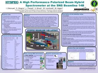
Outline HYSPEC: project timeline and place in the SNS instrument suite HYbrid SPECtrometer’s layout and principal features Polarized beam setup: principle and components Performance optimization of the (Fe/Si) transmission polarizer Summary and open questions Polarized Beam Operation of the Hybrid Spectrometer at the pulsed Spallation Neutron Source. Igor Zaliznyak Neutron Scattering Group, Brookhaven National Laboratory HYSPEC Instrument Design Team V. Ghosh, L. Passell and S. Shapiro (BNL), M. Hagen (SNS)
HYSPEC’s timeline • 2000 • Concept of the Hybrid Spectrometer proposed at BNL • 2001 • Direct Geometry Hybrid Spectrometer presented to SNS EFAC • HYSPEC Instrument Development Team (IDT) formed • 2002 • HYSPEC IDT filed Letter of Intent with SNS • HYSPEC proposal submitted to DOE • 2003 • DOE CD0, HYSPEC is approved as part of the SING project • 2004 • HYSPEC’s placement approved, design&engineering: real work begins • 2005 • DOE CD2, HYSPEC’s performance baseline approved • 2006 • DOE CD3, construction begins • 2011 • CD4, commissioning & beginning of operation
HYSPEC Teams. IDT Members and their Affiliations IDT Executive Committee S. M. Shapiro, co-PI BNL I. Zaliznyak, co-PI BNL D. Abernathy SNS L. Daemen LANL B. Gaulin McMaster J. Gardner BNL V. Ghosh BNL M. Greven Stanford M. Hagen SNS K. Hirota ISSP V. Kiryukhin Rutgers Y. Lee MIT C. Majkrzak NIST R. MQueeney Ames/Iowa St. U. S. Nagler ORNL R. Osborn ANL L. Passell BNL L. P. Regnault ILL J. Rhyne U. Missouri J. Tranquada BNL G. Xu BNL A. Zheludev ORNL • S. M. Shapiro, PI (BNL) • I. Zaliznyak, PI (BNL) • L. Passell (BNL) • R. McQueeney (Ames/Iowa St. U.) • J. Rhyne (LANL) • J. Tranquada (BNL) Instrument Design Team • I. Zaliznyak (BNL) • S. M. Shapiro (BNL) • L. Passell (BNL) • V. J. Ghosh (BNL) Monte-Carlo simulations • W. Leonhardt (BNL) Project Engineer • M. Hagen (SNS/BNL) Instrument scientist http://neutrons.phy.bnl.gov/HYSPEC
ARCS HYSPEC CNCS HYSPEC’s place in the SNS inelastic instruments suite. • High energy transfer • 10-1000 meV Fermi Chopper Spectrometer • E = 10 - 1000 meV • Q = 0.1 – 22 Å-1 epithermal • High intensity at moderate resolution and medium energy transfer + polarized beam • Crystal-Focussing Hybrid Spectrometer • E = 2.5 - 90 meV • Q = 0.1 – 8 Å-1 thermal • High resolution and low energy transfer • 10-100 meV Multichopper Spectrometer • E = 2 - 20 meV • Q = 0.1 - 4 Å-1 subthermal
Comparison of the HYSPEC performance with other inelastic instruments planned for the SNS MC simulations by SNS (G. Granroth and D. Abernathy) MCSTAS simulations by HYSPEC IDT (V. Ghosh), with different re-scaling for ARCS and SEQUOIA CNCS, ARCS and HRCS intensities were re-scaled to the same, coarser energy resolution as HYSPEC (this over-estimates their actual intensity)
HYSPEC layout and principal features To get more information, and for the project updates, please, visit http://neutrons.phy.bnl.gov/HYSPEC T0 Chopper T2 Chopper Monochromator Goniometer Radial Collimator or Bender Polarizers Flight Chamber (Ar/He filled) Detectors
HYSPEC layout in the polarized beam mode 18-20 transmission polarizers 2cm x 5cm (WxL) with 20’ Soller collimators upfront Heusler crystal monochromator, vertically focussed neutron spin flipper
HYSPEC polarization analysis: principle and experimental demonstration on SPINS at NIST Polarized beam Measurement with a Position Sensitive Detector (PSD) Heusler S.-H. Lee, C. F. Majkrzak, Physica B 267-268, 341 (1999)
HYSPEC polarization analysis: experimental demonstration with PSD on SPINS Nuclear and magnetic scattering intensities in La5/3Sr1/3NiO4 I. A. Zaliznyak and S.-H. Lee, in Modern Techniques for Characterizing Magnetic Materials, ed. Y. Zhu(to be published by Kluwer Academic, 2004)
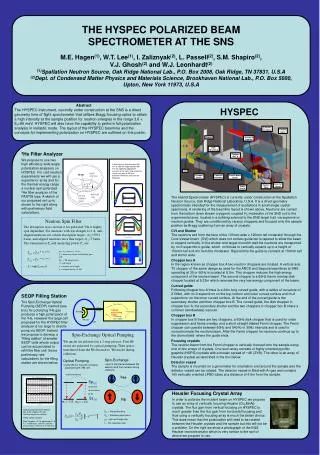
HYSPEC setup for polarization analysis • Polarized incident beam is supplied by reflection from the vertically focusing Cu2MnAl (Heusler alloy) crystal monochromator 10 meV < Eipol < 90 meV • Polarization analysis of the scattered neutrons is performed by a set of 18-20 supermirror-bender transmission polarizers, each 2 cm wide, 5 cm thick and 15 cm high, 3.7 meV < Efpol < 15-25 meV
Most important question: can we expect the transmission polarizers to work up to 15-25 meV? Performance of an optimized Fe/Si transmission polarizer for ~15 meV C. Majkrzak, Physica B 213&214 (1995) Yes, but fine-tuning of the polarizer tilt angle is necessary.
MC simulation (NISP) of HYSPEC operation in the polarized beam mode: beam separation Simulation for the bender geometry optimized for E=14.7 meV (C. Majkrzak, 1995) Sample-to-detector distance LSD is 4.5 m
The spatial separation of two polarizations for different sample-to-detector distances LSD = 3.5m θc(up) = 3.0 θcNi, θc(down) = 0.6θcNi. LSD = 3.0m LSD = 4.5m LSD = 4.0m The two polarizations only become sufficiently separated that they can be measured cleanly in the adjacent detector tubes for values of the secondary flight path LSD > 4.0m.
Optimizing geometry of the single-bounce transmission polarizer • Defining parameters are: • θc(up) and θc(down) • L, length • d, channel width • , tilt angle • β, bend angle • L ≈ 2R sin(β/2)≈ R β • Optimization considerations and constraints • θc(up) = 3.0 θc(Ni), θc(down) = 0.6 θc(Ni), => best we can imagine for now • L≈ 50 mm => maximum length is constrained by the transmission through Si • d ≤ R(1- cosβ) ≈ Lβ/2 ≈ 0.25 mm => to remove the line-of-sight • polarizer bend angle β => mechanically constrained, currently use 0.57° • polarizer tilt angle => must be optimized • Simple optimization condition for a single-bounce device • ( + β) = θc(up) = 3.0 θc(Ni)
Optimizing polarizer tilt angle at E = 3.7 meV = 0.3° 20’ collimator in front = 0.15° = 0.8° = 1.2° Neutron beam profiles on the detector
Optimizing polarizer tilt: E = 3.7 meV is quite “forgiving” Straight beam Deflected beam
Optimizing polarizer tilt angle at E = 10 meV 20’ collimator in front = 0.1° = 0.3° = 0.5° = 0.4° Neutron beam profiles on the detector
Optimizing polarizer tilt angle at E = 20 meV 20’ collimator in front = 0.0° = 0.2° = 0.4° = 0.3° Neutron beam profiles on the detector
Optimizing polarizer tilt: fine tuning is needed for higher energies Straight beam Deflected beam
A somewhat similar concept: D7 at ILL • Important differences of the proposed HYSPEC setup • optimized for thermal neutrons => optimized for using the straight-through transmitted beam => allows low-polarization-efficiency mode extending to high energies! • both spin states are measured by the detector array
Summary and open questions • Heusler monochromator provides polarized incident beam • Scattered beam polarization is determined by the array of transmission polarizers • straight-through transmitted beam is always measured • polarization sensitivity covers thermal neutron energies up to ~30 meV • all scattering angles are covered, ~2/3 of detectors are efficiently used • price in intensity paid for using 20’ collimators also buys lower background and somewhat better q-resolution • Fe/Si, Co/Si, other? • Optimization of the polarizer geometry for broadband operation • important to use the optimized tilt angle for every Ei, and E-range • curvature choice (possibly straight stack)? • fine tuning: length, channel width, collimation in front. • Effect of a coarse (2-3 degrees) radial collimator behind the polarizers?
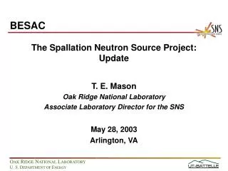
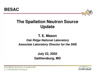
Spallation Neutron Source (SNS) at ORNL http://www.sns.gov/ http://www.sns.gov/partnerlabs/partners.htm
SNS accumulator ring built by BNL http://sns.bnl.gov/ http://sns.bnl.gov/ap_group/ring.html