Download
1 / 31
310 likes | 426 Vues
Overview of Beam Instrumentations for High-Power Operation of the Spallation Neutron Source. Saeed Assadi for SNS B.I. Group Beam Instrumentation Group Leaser SNS/ORNL. OUTLINE. Overview of Beam Instruments SCL Laser Profile Monitor Project Recent results Challenge Future plan.

E N D
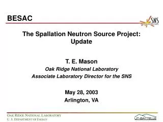
Overview of Beam Instrumentations for High-Power Operation of the Spallation Neutron Source Saeed Assadi for SNS B.I. Group Beam Instrumentation Group Leaser SNS/ORNL
OUTLINE • Overview of Beam Instruments • SCL Laser Profile Monitor Project • Recent results • Challenge • Future plan
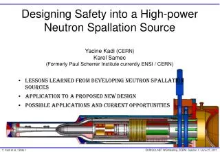
SNS Accelerator Complex Accumulator Ring: Compress 1 msec long pulse to 700 nsec Front-End: Produce a 1-msec long, chopped, H- beam Extraction Injection RF Liquid Hg Target 1 GeV LINAC 1000 MeV 2.5 MeV 87 MeV 186 MeV 387 MeV RTBT Ion Source HEBT DTL RFQ SRF,b=0.61 SRF,b=0.81 CCL Chopper system makes gaps 945 ns mini-pulse Current 700 nsec Pulse Accumulation 1 ms macro-pulse
Interceptive Beam Instrumentation Systems Operational RING 2 Wire-deleted IDump 2 Wire 2 IDump Video MEBT 5 Wires D-box emittance D-box beam stop D-box aperture 1 fast faraday cup 1 faraday/beam stop D-box video Edump 1 Wire CCL 8 Wire , 4BSM, 1 Faraday Cup RTBT 5 WireScanners 1 Harp 1 RTBT Video Target Video DTL 5 Wire 5 Faraday Cup SCL HEBT 5 Wire Scanners 2 BSM LDump 1 Wire CCL/SCL Transition 1 Wire
Non-Interceptive Beam Instrumentation Systems IDump 1 Position1 Current 2 BLM RING 2 Electron Profile Scanner 5 Electron Det. 12 FBLM 1 Beam in Gap Monitor 1 Tune, 84 BLMs, 4 NDs 2 Transverse feedback system MEBT 2 Thermal Neutron 3 PMT Neutron D-box Mode-lock laser 2 Beam-Gap Monitor [ChuMPS] 6 BPMs 2 BCMs 1 Mode-lock laser Operational Not Operating EDump 4 BLM, 1 BCM CCL 8 Neutron, 2 Thermal 48 Loss RTBT 1 Movable Harp 3 FBLM 26 BPMs 26 BLMs DTL 2 Beam-Gap Monitor [ChuMPS] 3 Diff BCM Monitor 6 Thermal and 12 PMT Neutron 6 Current, 12 BLMs SCL 32 Position 86 Loss 9 Laser Wire 1 Laser Wire 24 PMT Neutron HEBT 29 Position 1 Laser Beam in-gap 1 Laser emittance sys 48 BLMs, 4FBLM LDump 2 Loss 1 Wire ,1 BCM 5 position CCL/SCL Transition 2 Position 1 Loss 1 Current
Quick History and Facts about SNS The SNS is a short-pulse neutron source, driven by a 1.4 MW proton accelerator [ presently at .54 MW]. SNS will be the world’s leading facility for neutron scattering research with peak neutron flux ~20–100x ILL, Grenoble SNS construction project, a collaboration of six US DOE labs, was funded through DOE-BES at a cost of 1.4 B$ SNS will have 8x beam power of ISIS, the world’s leading pulsed source user facility, Stepping stone to other high power facilities, expected to achieve 1.4 MW in two years.
Motivation to Add &/or Modify More Beam Instruments • Improve reliability • Improve user friendliness – i.e. automation, additional features – • Support, diagnose “unexpected” events – i.e. Spark detectors, LEBT and RFQ RGAs • Accelerator Physics requests – Laser emittance system. • Allow “parasitic” studies; IPM, electron profile monitor. Different types of BLMs.
Continue: Motivation to Add &/or Modify More Beam Instruments • 60 Hz Beam Accounting [Never was in the plan] • Low Energy Beam Loss Measurements , WGF4- A. Zhukov’s talk • Differential Current Measurements in DTL/CCL • High Power Operations.– e/p Instabilities, use of digital active transverse feedback system for the Ring. WG F- (wed) – Craig Deibele’s talk • Ring Electron Profile Monitor, BINP collaboration with SNS, initial results by W. Blokland in this talk. • Computation of Space-Charge Effects in Allison Scanner and Its Application to the Measurement of Emittance by TimofeyGorlov
ORNL-SNS Laser Diagnostic Activities • MEBT Mode-lock laser initially in 1-D – 9/2004 • SCL Nd:YAG 1064 nm Laser, 9-station – 9/2005 • Laser Stripping test Nd:YAG, 3ed harmonic -- 8/2005 • Working on making SCL Laser system turn-key -- to present SCL Laser Profile Monitors, 9-stations MEBT 3-D Laser Profile Monitor 4M 1D 4H Laser Striping Experiment Laser Emittance
What does the Laser do? Photo-neutralization H- H0 + e hn • Requirements • High peak power • Small spot size • Transverse scan • Temporal stability • Detection Ibeam 12ns -H- time Cross-section is well known therefore stripping efficiency calculation is a matter of algebraic manipulation
Photodetachment S hn H- H0 H0 e N Faraday Cup Principle of Laser Wire, direct electron current measurement at SNS. • Detected electron number is proportional to the ion density
Laser Room • Q-switched Nd:YAG laser • l = 1.06 mm • frep = 30 Hz, Tw = 7 ns • Ep = 50 – 200 mJ • Injection seeded • Timing synchronized to SCL Redundant Lasers are available for the SCL. • High pulse energy • Small spot size • Single wavelength • Pointing stability • Temporal stability Requirements:
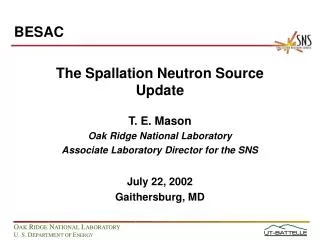
Layout of the SCL Laser Wire System Camera Mirror Power meter Laser room Laser wire station Cryomodule number LR LR 32 1 2 3 4 5 12 13 14 15 17 32 250 m 227 m 160 m 25 m Ring Target MEBT DTL CCL SCL • 4 LW from 200 MeV • 4 LW from 450 MeV • 1 LW at 1 GeV
SCL Laser Transport Line Q-switched Nd:YAG laser 1064 nm 30 Hz 7 ns Up to 1.5 J Injection seeded
From LTL Flip-Mirror Mirror H-scan Lens Beam Dump V-scan Photodiode Ion Beam Schematic of Laser Wire Station Optics
Top-Level Software Controls all Stations and collects Data. LW Station Diagnostics Profile Measurement User specifies station, axis, scanning range/step/ave. number, controls timing, and data acquisition User monitors laser beam position, lens focus, electron collector output raw signal
Effects of LW Magnet Current Magnet Current (A) 0 1 2 3 4 5 6 7 8 9 10 11 12 13 14 LW Station 02 LW Station 15 LW Station 32 Falling edge cut Rising edge cut Normal profile
One challenge that is solved Effects of LW Magnet Current Vertical Beam Profile Measurement at LW32 Magnet Current (A) 12.9 12.4 11.9 11.4 10.9 10.4 9.9 9.4 8.9 8.4 7.9 7.4
Advantage of Laser is to be able to scan the entire Macro-pulse. Mini-pulse #1 #100 #200 #300
Beam Profile Measurements LW1 LW5 LW9
Laser beam Ion beam S f Yd Ion beam Laser beam S f Realistic Laser Beam with respect to H- Laser beam shifts on the lens surface Laser beam shifts + Ion beam shifts from waist
Yd Ion beam Laser beam S f Challenge! Experimental Measurements Why do we get poor profiles in this case
Current Laser Wire Box f2.75 3.5 5 3.25 4 12 13.5 6.5 f2-3/8 11.5 5.75 3.25 2.75 14 rear front 1 f2-3/8 4.5 f2.5 f2.5 7.25 3.5 6.5 2.75 1 12 6.75 11.5
Revised Laser Wire Box Design to Bring Larger Travel Range f2.75 3.5 5 3.25 4 12 13.5 6.5 f2-3/8 11.5 3.25 2.75 14 1 f2-3/8 4.5 f2.5 f2.5 7.25 6.5 2.75 1 12 6.75 11.5
SUMMARY of Laser Profile Monitor • Profiles have been measured at all 9 stations • Operational parameters have been investigated and optimized • Software platform has been improved • Issues of radiation and stability are looked into and solutions are provided • Future plan • Secure system reliability • Optimize/document operational procedure • Identify technical problems and work on solutions
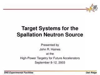
Phosphor screen MCP Photo camera Electron beam Transverse Profile Monitor Layout of the proposed EBP for SNS Accumulator Ring by BINP Quadrupole lens Deflector Electron Gun Proton beam 750 600
Collaboration on Design and Construction of Electron Beam Profile Monitor Between SNS-ORNL and BINP, Novosibirsk, Russia has started Probe beam: Energy=75keV, Scan.-parallel, 3rd ,4th quads - ON Proton beam: Energy=1GeV Np=1*1013 Transverse size r=1.5cm Round uniform transverse distribution Simulation Alexander Starostenko Blue line – theoretical profile, Magenta + square – reconstructed profile 28
Horizontal Profile after 500 turn, 8 Micro-Coulomb of charge in the Ring.
Vertical Profile after 500 turn, 8 Micro-Coulomb of charge in the Ring ---- Another useful tool!