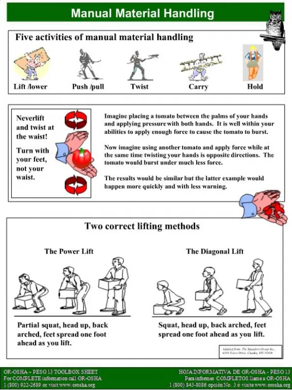
Lift
2. . L = C. S. V. X. X. X. L. Lift. The component of the total aerodynamic force of an airfoil that is perpendicular to the resultant relative wind. 90°. TAF. Lift. Resultant Relative Wind. Factors affecting lift. C L (coefficient of lift)
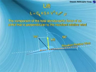

Lift
E N D
Presentation Transcript
2 L = C S V X X X L Lift The component of the total aerodynamic force of an airfoil that is perpendicular to the resultant relative wind 90° TAF Lift Resultant Relative Wind
Factors affecting lift • CL (coefficient of lift) • Surface area of the airfoil measured in square feet. • Air density measured in slugs of air per cubic foot. • V (relative wind velocity in feet per second)
CL (coefficient of lift) A dimensionless number, determined through wind tunnel tests. Denotes the lift producing capability of an airfoil Values range from 0 to 2 or more Factors that determine the value of CL include • Shape and design of an airfoil • Angle of Attack
S (surface area) • Measured in square feet • Physically constant, but effective size can be changed by other variables
Air Density = rho Measured in slugs of air per cubic foot. A cubic foot of standard day air has a mass of .002377 slugs. Factors affecting air density • Pressure density increases as pressure increases. Density decreases with altitude because pressure decreases • Temperature density decreases as temperature increases • Humidity density decreases as water vapor content increases
V (relative wind velocity, feet per second) Lift increases with the square of wind velocity
The CL/CD ratio resulting in the largest quotient is referred to as L/D . L/D ratios also indicate optimum glide ratio of an airfoil. max Lift/Drag ratio (L/D) Any airfoil operates at its maximum efficiency at one angle of attack, that angle of attack must be determined. Airfoil designers can determine the best angle of attack by dividing the CL by the CD for a number of angles of attack.
2.0 20 .200 .180 18 C/L 16 .160 L/D Max C/L .140 14 Max .120 12 C/D .100 1.0 10 L/D 8 .080 .060 6 .040 4 .020 2 .0 0 0° 2° 4° 6° 8° 10° 12° 14° 16° 18° 20° 22° Angle of Attack Lift to Drag Ratio C/D Highest Lift C/L to Drag L/D Ratio Stall
Lift Lift and Thrust Resultant Lift of the Rotor System To maneuver the helicopter, the tip path plane must be tilted in the desired direction of movement. Tilting the rotor disk will create a horizontal thrust component, the lift component will be decreased and must be compensated for with collective
Question What combination of temperature, pressure and humidity would produce the greatest air density? Answer: Low temperature, high pressure, and low humidity
Enabling Learning Objective #7 From memory, the student will describe, by writing or selecting from a list, the three types of drag and identify the factors affecting drag IAW FM 1-203
Drag The resistance to an object’s passage through the air Types of Drag Induced Profile Parasite
Induced Drag • Drag that is incurred as a result of the production of lift • Parallel to and in the same direction as relative wind • Increases with increased angle of attack • Decreases with increased airspeed Each blade passes through the previous blade’s disturbed air this condition is most pronounced at high power settings and no or low forward airspeeds.
Profile Drag • Parasitic drag of the rotor system • At a constant RPM, profile drag is relatively constant but does increase slightly with airspeed. • Increases rapidly with very high airspeeds due to onset of blade stall or compressibility • Profile drag is greater on 3, 4, 6, etc. bladed systems
Parasitic Drag The resistance offered by the fuselage and other nonlifting surfaces to the flow of air Causes • Form or shape of the helicopter, the more streamlined the helicopter, the less parasitic drag • Skin friction, the smoother the skin of the fuselage, the less parasitic drag Increases rapidly with airspeed
Total Drag Curve The summation of all drag forces acting on the helicopter Total drag is high at a hover, decreases to a minimum value at a particular airspeed, then starts increasing with airspeed Minimum rate of descent for autorotation Maximum endurance airspeed Maximum rate of climb airspeed Best maneuvering airspeed The above are airspeeds that fall within the lowest drag area of the total drag curve. Theses speeds typically range from 60 to 80 kts
Drag Forces Torque Available Parasite Drag Total Drag Profile Drag Drag Induced Drag Forward Speed