Download
1 / 27
270 likes | 285 Vues
Investigating state-of-the-art sensor technology for urban biological threat detection, fusion of sensor data, and its communication algorithms.

E N D
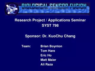
Research Project / Applications Seminar SYST 798 PROGRESS REPORT 6 March 2008 Team: Brian Boynton Tom Hare Eric Ho Matt Maier Ali Raza Key Sponsor: Dr. Kuo-Chu Chang
What is Biological Sensor Fusion? • The Modeled Use Case • Smallpox released on the order of 100 billion organisms to contaminate a heavily trafficked urban area • Terrorists could simply spray the pathogen into the air • System Context • Within a city the size of Chicago there is a potential for 575,000 deaths or more • Current response plans would not allow for detection or response before 3-4 days • Our Model will investigate employment of state of the art technology that will not be applied for another 10 years
What is Biological Sensor Fusion? (cont.) • System Context (cont.) • Tier I Sensors: Stationary Sensors • Permanently Situated in our Modeled Chicago Police District 001 • Tier II Sensors: Mobile Ad Hoc Sensors • Deployed in emergency response vehicles • Responsible for plotting a epidemic dispersion trajectory • Tier III Sensors: Stationary Ad Hoc Sensors • Deployed after a threat is already confirmed • As technology evolves, would provide high-regret tracking of dispersion • Accuracy prioritized over fast detection • False alarms that shut down facilities and displace people can rival the cost of an actual outbreak (~$750 billion) • After discussion with Subject Matter Expert, realistic, accurate detection time is 4-8 hours; this will reduce over time • Current sensor capabilities include 100m3 /minute “sniffing” • Current detection sensitivity: 100 target organisms/18m3
What is Biological Sensor Fusion? (cont.) • Model Communications and Fusion • Communications: Using algorithms designed for ad-hoc sensor deployment: • Epidemic-SI • Epidemic-SIS • Epidemic-SIR • Gossip • Gossip Enforced Ending • Geocasting • Greedy Forwarding • Geographic Face Routing • Fusion: Aggregation of data both at sensors and at Operations Center • Expected Result: Find the fastest method to accurately sense and fuse all data to cordon off and respond to an urban biological threat 1 3 2 7 5 6 4 8
Progress So Far (Progress since last report) • Problem Definition/ Requirements Engineering (75%) • Use Case, Context Diagram, Operational Scenarios Complete • Project Requirements and Requirements Derivation • Research (60%) • Urban Sensors: 14 companies contacted/researched about future sensor developments - Northrop Grumman Systems Corporation, MicroFluidic Systems, SAIC, U.S. Genomics, IQuum, and Nanolytics • City of Chicago: Contacted Deputy Director, Homeland Security & Emergency Management for the City of Chicago • Biological Threats: disease characteristics for Smallpox and Anthrax • Data Algorithms and Fusion: 19 research papers provided by sponsor on epidemic, gossip, geographic and other algorithms (up from 7) • 59 articles/papers researched & referenced so far (up from 29) • Ongoing Research: Still reviewing solicitations on DHS Website
Progress So Far (Progress since last report) • Development (50%) • Architecture Products Complete: • OV-1 High Level Operational Concept • OV-2 Operational Node Connectivity Description • OV-5 Operational Activity Model • OV-6c Operational Event-Trace Description • SV-4 Functionality Description • Model Development: • Modeling Parameters Selected • Modeling Approach • CPN stochastic model of “small world network” data flow times based on range • Java model of geographic placement of ad-hoc sensors, with epidemic modeling and sensor communications paths • Management (50%) • Proposal Update with Sponsor Comments • WBS Update with Sponsor Comments • EVMS Update with Sponsor Comments • Project Schedule • Team Communications (50%) • Web Site Update • Online Meetings • Sponsor Events
Architecture Discussion • We will get 3 major benefits from developing an architecture for our Sensor System • Establish a Clear View as to the Logistics of our Program • You get a complete and multi-faceted view of your system so as to be able to understand it better. This, in turn, increases the accountability for whomever is delivering the system • Develop an executable model from the culmination of the architecture products so as to be able to furnish a live simulation of how the system will work
Activity Model Executable Model • The CPN Executable is obtained from different Product views, the IDEF0 (for example): • To each IDEF0 model page corresponds a CPN model page. • The CPN model has the same hierarchical structure as the IDEF0 model • The activities in the IDEF0 diagram are converted to transitions: • Decomposed activities are represented by substitution transitions that represent the CPN model page corresponding to the IDEF0 page of the decomposition
What’s Next • Java Model • Add Tier I and Tier II Mobile Sensors • Add map display • Add more communication algorithms (additional Epidemic, Geographic) • Add additional communications parameters • Add cordon/fusion determination • CPN Model • Investigate model scalability and parameter determination • Architecture • Operational Information Exchange Matrix (OV-3) • Systems Interface Description (SV-1) • Systems Communication Description (SV-2) • Operational Activity to System Function Traceability Matrix (SV-5) • Systems Data Exchange Matrix (SV-6) • Systems Performance Parameters Matrix (SV-7) • Reporting • Model Execution/ Analysis • EVM • Progress Reports (x2), Status Reports (x1) • Final Report
Why is this effort important? • Biological Sensor Fusion • Saves lives • Reduces vaccination/ cleanup/ decontamination costs • Provides faster response than times today • Fuses data for responders to target a threat real-time • Is high interest research area in DoD and DHS today • Demonstrates the use of ad-hoc and mobile ad-hoc communications in a real-world scenario
U.S. Interest • Bioterrorism Response Tomorrow • Both DHS and DoD recognize the need for urban biological sensor detection • 2003 • Biowatch is created to deploy a national urban sensor network. Using up to 50 sensors per city, Biowatch is designed to provide coverage for 80 percent of the population in urban environments to detect a biological agent within 36 hours of release and give authorities time to react properly. • 2005 • DARPA spends $110-155M annually to develop biological sensors with faster response times using DNA and RNA detection and electromagnetic radiation • 2008+ • A number of companies invest in small, very fast, high accuracy sensors to detect biological threats Go back
This view will summarize and expand the characteristics of the exchanged information captured in OV-2. The exchanged information’s attributes such as information content, classification, periodicity, criticality, and timeliness will be included in this view. OV-3 Operational Information Exchange Matrix
This view will capture the communication pathway of the system. All communication nodes that help transmit data among the systems will be captured. SV-2 Systems Communications Description
This view will map the operational activities captured in OV-5 with functions captured in SV-4 to show how the operational requirements/capabilities can be supported by system’s capabilities. SV-5 Operational Activity to Systems Function Traceability Matrix
This view will capture more details of the data exchanged among systems. Exchanged data’s attributes such as data content, format, criticality, periodicity, timeliness, classification, and communication entry point will be captured in this matrix. SV-6 System Data Exchange Matrix
This view will capture the performance parameters of the system. All sensors’ performance parameters will be captured along with those of C2 systems. SV-7 Systems Performance Parameters Matrix
The OV-1 depicts the operational concept for BSF: to model communication and fusion of a multi-tier ad-hoc sensor network in Chicago Police District 001. OV-1 – Operational Concept Graphic
The OV-2 lists all operational nodes/stakeholders of the system, and also the information needed to be exchanged among these nodes. In this architecture, all sensor nodes and Command and Control (C2) centers will be captured along with all information exchanged among them. OV-2 - Operational Node Connectivity Description
The OV-5 depicts a high-level operational activity process of the system. It includes the high-level activities of sensors and Command and Control centers and their functional decomposition. OV-5 Operational Activity Model
The OV-6c captures different scenarios/use cases of the operational concept. This view depicts the time-based information flow processes of the activities captured in OV-5. OV-6c Event Trace Description
The SV-1 captures the internal and external interfaces of this system. It includes sensor-sensor interfaces, sensor-C2’s system, and C2’s system-C2’s system. SV-1 Systems Interface Description
The SV-4 captures the high-level functionalities of the system. It will capture the sensor’s functionalities, C2’s system’s functionalities. SV-4 Systems Functionality Description