Download
1 / 26
260 likes | 422 Vues
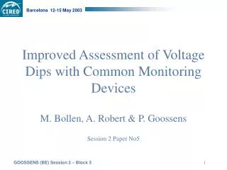
Improved Assessment of Voltage Dips with Common Monitoring Devices. M. Bollen, A. Robert & P. Goossens Session 2 Paper No5. Voltage Dip Representation. Why Voltage Phasors? Limitations of RMS-representation. Dip produced by single phase fault. single phase dip. 2-phase dip. Depth = 36 %.

E N D
Improved Assessment of Voltage Dips with Common Monitoring Devices M. Bollen, A. Robert & P. Goossens Session 2 Paper No5
Voltage Dip Representation Why Voltage Phasors? Limitations of RMS-representation
Dip produced by single phase fault single phase dip 2-phase dip Depth = 36 % Depth = 16 %
D y Dip produced by single phase fault • MAGNITUDE (PP) • U1 = 94% • U2 = 80% • U3 = 93% primary side trafo secondary side trafo
Why phasors? • indication about origin • fault type and characteristics • dip propagation • through transformers • connection : star or delta • depth: phase-to-ground phase-to-phase
Improved Dip Characterisation (M. Bollen) Voltage Type: A, B, C, D, E, F & G Characteristic Magnitude V Phase Angle Jump
7 Dip Types 4 types of faults • 3-phase faults • 1-phase faults • 2-phase faults • 2-phase-to-ground faults • propagation through transformers • delta or star connection Seven types of voltage dips A B (C, D) C (D) E (F, G)
Dip Type A Origin: balanced three phase fault « A »
Dip type B, C & D « B » origin: single phase faultstar connection « D » « C » 2-phase fault, delta connection origin: 2-phase fault, star connectionor single phase fault, delta connection
Dip Type E, F & G Connection: star Origin: 2-phase to ground « G » « E » « F » Connection: delta Connection: delta Behind Dy or Yd trafo
Fault Type Dip Location I II III 3-phase A A A 3-phase-to-ground A A A I 2-phase-to-ground E F G Yd 2-phase C D C II 1-phase-to-ground B C D Dy III Propagation of voltage dips line & phase voltages are swapped: rms-voltages changes !
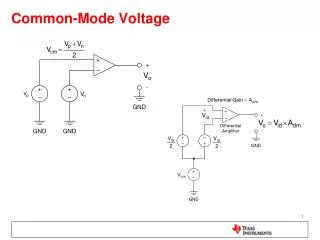
V V Characteristic Voltage Characteristic Magnitude V &Phase Angle Jump • A, C, D, F, G: MIN(3 UPN & 3 UPP) • B, E: first remove U0 = Invariable of connection type (PP PG) and location (primary secondary trafo)
Voltage Dip Conversion Algorithms RMS PHASORS
Why conversion algorithms? Common power quality monitors only measure rms-voltages during dip Voltage phasors interesting / required for analysis / statistics conversion!
Rms phasors algorithm 2 STEPS: • step 1: determine type of dip • from relation between the three rms-voltages • number of possible dips is limited • step 2: determine dip characteristics & phasors • 3 rms-voltages & dip type the characteristic voltage V and phase-angle jump can be estimated
Step 1: determine dip type (1) • A : three-phase drops • C, E and G: two-phase drops • B, D and F: single-phase drops Umin Umax Voltage Dip Type
Step 1: determine dip type (2) 1 & 3 phase drops 2 & 3 phase drops
Step 2: determine characteristic voltage & phase angle jump 3 rms voltages U1, U2, U3 dip type C characteristic voltage & phase angle jump voltage phasors
RMS Voltage Phasorsfor PP measurements • no zero-sequence component • 3 phasors makes up closed triangle phasors can easily be estimated out of 3 rms voltages with trigonometry equations
Evaluation of algorithms • check of twenty voltage dips in Belgium HV-stations • accuracy better than 5% for 95% of dips: acceptable for statistical purposes • fine tuning of algorithms in progress
Monitor spec’s Best solution: recording of rms & phasor evolution during voltage dip Alternative: only rms recordings to be able to apply conversion algorithms • all three rms-voltages must be recorded during voltage dip • snapshot of three rms-voltages when maximum depth is reached if necessary: adapt firmware of monitor
Connection of monitor (rms) phase-to-phase measurement (PP) • phasors can be calculated with trigonometry equations (closed triangle) • propagation of voltage dips can be estimated accurately • no indication about the origin phase-to-ground measurement (PN) • often preferable because indication about origin • propagation can be estimated with proposed algorithms
Voltage dip statistics (depth & length) • phase-to-ground phase-to-phase statistics • not comparable & should never be mixed • always mention which connection is considered in tables or statistics (PG or PP) • avoid phase-to-ground statistics • too pessimistic view • especially in impedance grounded systems • zero-sequence component is removed in Yd and Dy transformers
Voltage dip statistics (depth & length) • phase-to-phase statistics are preferable • can be derived from phase-to-ground measurements with proposed algorithms • alternative: statistics with characteristic magnitude • characteristic magnitude can be estimated with proposed algorithms, • remains invariable during propagation (primary or secondary side trafo) • is independant of connection