Valence Bond Theory
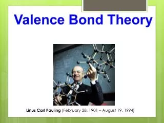
Valence Bond Theory. How do bonds form?. The valence bond model or atomic orbital model was developed by Linus Pauling in order to explain how atoms come together and form molecules.

Valence Bond Theory
E N D
Presentation Transcript
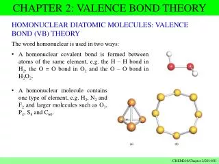
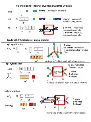
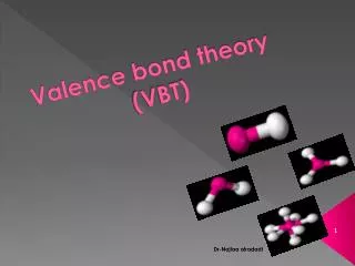
How do bonds form? • The valence bond model or atomic orbital model was developed by Linus Pauling in order to explain how atoms come together and form molecules. • The model theorizes that a covalent bond forms when two orbitals overlap to produce a new combined orbital containing two electrons of opposite spin. • This overlapping results in a decrease in the energy of the atoms forming the bond. • The shared electron pair is most likely to be found in the space between the two nuclei of the atoms forming the bonds.
Example H2 • The newly combined orbital will contain an electron pair with opposite spin just like a filled atomic orbital.
Example HF • In hydrogen fluoride the 1s orbital of the H will overlap with the half-filled 2p orbital of the F forming a covalent bond.
Other Points on the Valence Bond Theory • This theory can also be applied to molecules with more than two atoms such as water. • Each covalent bond results in a new combined orbital with two oppositely spinning electrons. • In order for atoms to bond according to the valence bond model, the orbitals must have an unpaired electron.
Covalent Bonding: Orbitals Hybridization • The mixing of atomic orbitals to form special orbitals for bonding. • The atoms are responding as needed to give the minimum energyfor the molecule.
sp3 Hybridization The experimentally known structure of CH4 molecule can be explained if we assume that the carbon atom adopts a special set of atomic orbitals. These new orbital are obtained by combining the 2s and the three 2p orbitals of the carbon atom to produce four identically shaped orbital that are oriented toward the corners of a tetrahedron and are used to bond to the hydrogen atoms. Whenever a set of equivalent tetrahedral atomic orbitals is required by an atom, this model assumes that the atom adopts a set of sp3 orbitals; the atom becomes sp3 hybridized.
Figure 9.5. An Energy-Level Diagram Showing the Formation of Four sp3 Orbitals
Figure 9.2. The Valence Orbitals on a Free Carbon Atom: 2s, 2px, 2py, and 2pz
Figure 9.9. An Orbital Energy-Level Diagram for sp2 Hybridization
Figure 9.8. The Hybridization of the s, px, and py Atomic Orbitals
A sigma () bondcenters along the internuclear axis. end-to-end overlap of orbitals • A pi () bondoccupies the space above and below the internuclear axis. side-to-side overlap of orbitals
Figure 9.16. The Orbital Energy-Level Diagram for the Formation of sp Hybrid Orbitals on Carbon
Figure 9.14. When One s Orbital and One p Orbital are Hybridized, a Set of Two sp Orbitals Oriented at 180 Degrees Results
Figure 9.18. The Orbital Arrangement for an sp2 Hybridized Oxygen Atom
Figure 9.21. A Set of dsp3 Hybrid Orbitals on a Phosphorus Atom
Figure 9.23. An Octahedral Set of d2sp3 Orbitals on a Sulfur Atom
Figure 9.24. The Relationship of the Number of Effective Pairs, Their Spatial Arrangement, and the Hybrid Orbital Set Required
The Localized Electron Model Three Steps: • Draw the Lewis structure(s) • Determine the arrangement of electron pairs (VSEPR model). • Specify the necessary hybrid orbitals.
Paramagnetism • unpaired electrons • attracted to induced magnetic field • much stronger than diamagnetism